Panasonic P2 HD Camcorder Operating Instructions - Page 86
Setting the Marker Displays, Marker Check Screen Displays (MARKER SELECT button function)
 |
View all Panasonic P2 HD Camcorder manuals
Add to My Manuals
Save this manual to your list of manuals |
Page 86 highlights
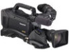
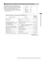
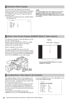
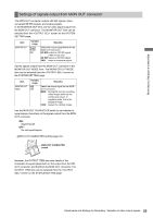
Setting the Marker Displays The center, safety zone, safety zone area and frame markers may be set to ON or OFF, along with specifications of the marker types. To set and select markers, go to the screen from the VF page and select the appropriate options. > For directions on navigating the menu, see [Setting Menu Options] (page 160). # < VF MARKER > MKR:A TABLE :A CENTER MARK :1 SAFETY MARK :2 SAFETY AREA :90% FRAME MARK :OFF FRAME SIG :4:3 FLAME LVL :15 ‹Note The indication MKR:A at the upper right of the screen shows the current indication status. To view TABLE B, press the MARKER SEL, MODE CHK / MENU CANCEL switch on the unit. This changes the indication to MKR:B, allowing you to view the set conditions. Marker Check Screen Displays (MARKER SELECT button function) The viewfinder can display a screen that allows you to view the marker settings of the unit. When you press the MARKER SEL, MODE CHK / MENU CANCEL switch on the side of this unit, the marker displayed by the viewfinder changes. Marker A > Marker B > No marker If the menu item FRAME SIG is set to 16:9 as the information of Marker A and 4:3 as the information of Marker B, then the 16:9 and 4:3 view angles can easily be checked with the button, as required. The menu item FRAME SIG is found in the screen on the VF page. Markers Center marker Safety zone The view angle specified through the menu option FRAME SIG is displayed. MARKER SEL, MODE CHK / MENU CANCEL switch Checking Return Video Signal in the Viewfinder The viewfinder displays the return video signal input to the GENLOCK IN or SDI IN connector while the RET button at the lens is held down. To enable this function, select "CAM RET" for the menu option RET SW. In HD (1080i) mode, either the HD SDI signal from the SDI IN connector, or the HD-Y signal from the GENLOCK IN connector in the RETURN SIGNAL item can be selected. In SD mode, only the SD SDI signal from the SDI IN connector can be viewed. The menu item RETURN SIGNAL is found in the screen on the SYSTEM SETTING page, and the menu item RET SW is found in the screen on the CAM OPERATION page. < SW MODE > # RET SW :R.REVIEW S.BLK LVL :-10 AUTO KNEE SW :ON SHD.ABB SW CTL :ON COLOR BARS :SMPTE S.GAIN OFF :L/M/H DS.GAIN OFF :DS.GAIN D.ZOOM a2 :ON D.ZOOM a3 :ON D.ZOOM a4 :ON RC CHECK SW :R.REVIEW 86 Adjustments and Settings for Recording : Viewfinder Screen Status Displays
-
 1
1 -
2
-
3
-
4
-
5
-
6
-
7
-
8
-
9
-
10
-
11
-
12
-
13
-
14
-
15
-
16
-
17
-
18
-
19
-
20
-
21
-
22
-
23
-
24
-
25
-
26
-
27
-
28
-
29
-
30
-
31
-
32
-
33
-
34
-
35
-
36
-
37
-
38
-
39
-
40
-
41
-
42
-
43
-
44
-
45
-
46
-
47
-
48
-
49
-
50
-
51
-
52
-
53
-
54
-
55
-
56
-
57
-
58
-
59
-
60
-
61
-
62
-
63
-
64
-
65
-
66
-
67
-
68
-
69
-
70
-
71
-
72
-
73
-
74
-
75
-
76
-
77
-
78
-
79
-
80
-
 81
81 -
 82
82 -
 83
83 -
 84
84 -
 85
85 -
 86
86 -
 87
87 -
 88
88 -
 89
89 -
 90
90 -
 91
91 -
92
-
93
-
94
-
95
-
96
-
97
-
98
-
99
-
100
-
101
-
102
-
103
-
104
-
105
-
106
-
107
-
108
-
109
-
110
-
111
-
112
-
113
-
114
-
115
-
116
-
117
-
118
-
119
-
120
-
121
-
122
-
123
-
124
-
125
-
126
-
127
-
128
-
129
-
130
-
131
-
132
-
133
-
134
-
135
-
136
-
137
-
138
-
139
-
140
-
141
-
142
-
143
-
144
-
145
-
146
-
147
-
148
-
149
-
150
-
151
-
152
-
153
-
154
-
155
-
156
-
157
-
158
-
159
-
160
-
161
-
162
-
163
-
164
-
165
-
166
-
167
-
168
-
169
-
170
-
171
-
172
-
173
-
174
-
175
-
176
-
177
-
178
-
179
-
180
-
181
-
182
-
183
-
184
-
185
-
186
-
187
-
188
-
189
-
190
-
191
-
192
-
193
-
194
-
195
-
196
-
197
-
198
-
199
-
200
-
201
-
202
-
203
-
204
-
205
-
206
-
207
-
208
 |
 |
