Panasonic PT-D7700U-K Dlp Projector - English/ French - Page 106
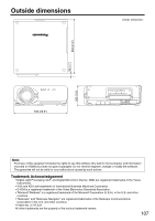
Appendix
 |
UPC - 791871111000
View all Panasonic PT-D7700U-K manuals
Add to My Manuals
Save this manual to your list of manuals |
Page 106 highlights
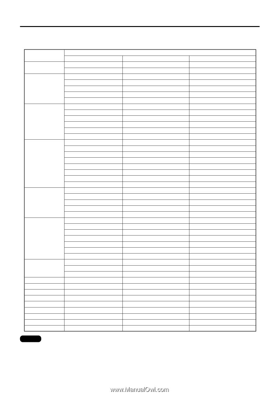
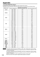
Appendix The following table specifies the types of RGB/ YPBPR signals compatible with the projector. RGB signals can also be input within the range of fH=15 kHz-100 kHz, fV=24 Hz-120 Hz, dot clock=20 MHz-162 MHz. Display mode VGA400 VGA480 SVGA XGA MXGA SXGA SXGA+ UXGA MAC16 MAC21 1080 / 60i 720 / 60p 480i 576i 480p 576p Number of displayed dots 640 x 400 640 x 400 640 x 480 640 x 480 640 x 480 640 x 480 640 x 480 800 x 600 800 x 600 800 x 600 800 x 600 800 x 600 800 x 600 1 024 x 768 1 024 x 768 1 024 x 768 1 024 x 768 1 024 x 768 1 024 x 768i 1 024 x 768 1 024 x 768 1 152 x 864 1 152 x 864 1 152 x 864 1 120 x 750 1 120 x 750i 1 280 x 1 024 1 280 x 1 024 1 280 x 1 024 1 280 x 1 024 1 280 x 1 024 1 280 x 1 024i 1 280 x 1 024i 1 400 x 1 050 1 400 x 1 050 1 400 x 1 050 1 600 x 1 200 832 x 624 1 152 x 870 1 920 x 1 080i 1 280 x 720 720 x 480i 720 x 576i 720 x 483 720 x 576 Applicable input signal data Horizontal scanning frequency (kHz) 24.8 31.5 31.5 35.0 37.9 37.5 43.3 32.1 35.2 37.9 48.1 46.9 53.7 48.4 56.5 60.0 65.5 68.7 35.5 80.7 94.0 63.9 67.5 77.1 50.1 32.6 52.4 64.0 78.2 80.0 91.2 46.2 47.6 65.2 78.8 82.2 75.0 49.7 68.6 33.75 45.0 15.7 15.6 31.5 31.25 Vertical scanning frequency (Hz) 56.4 70.1 59.9 66.7 72.8 75.0 85.0 51.0 56.3 60.3 72.1 75.0 85.1 60.0 70.1 75.0 81.6 85.0 86.8 100.8 120.0 70.0 75.0 85.0 60.1 80.0 50.0 60.0 71.7 75.0 85.0 86.0 88.9 60.0 72.0 75.0 60.0 74.6 75.0 60.0 60.0 59.9 50.0 59.9 50.0 Note 106 • The number of display dots of the PT-D7700U is 1 400 x 1 050. If signals with a number of display dots differing from the data listed above are supplied, they will be converted into signals with 1 400 x 1 050 dots and displayed. • The number of display dots of the PT-DW7000U is 1 366 x 768. If signals with a number of display dots differing from the data listed above are supplied, they will be converted into signals with 1 366 x 768 dots and displayed. • Character "i" that follows the number of displayed dots stands for interlace signal. • Flicker (line flicker) will be caused in images if interlace signals are connected.
-
 1
1 -
2
-
3
-
4
-
5
-
6
-
7
-
8
-
9
-
10
-
11
-
12
-
13
-
14
-
15
-
16
-
17
-
18
-
19
-
20
-
21
-
22
-
23
-
24
-
25
-
26
-
27
-
28
-
29
-
30
-
31
-
32
-
33
-
34
-
35
-
36
-
37
-
38
-
39
-
40
-
41
-
42
-
43
-
44
-
45
-
46
-
47
-
48
-
49
-
50
-
51
-
52
-
53
-
54
-
55
-
56
-
57
-
58
-
59
-
60
-
61
-
62
-
63
-
64
-
65
-
66
-
67
-
68
-
69
-
70
-
71
-
72
-
73
-
74
-
75
-
76
-
77
-
78
-
79
-
80
-
81
-
82
-
83
-
84
-
85
-
86
-
87
-
88
-
89
-
90
-
91
-
92
-
93
-
94
-
95
-
96
-
97
-
98
-
99
-
100
-
 101
101 -
 102
102 -
 103
103 -
 104
104 -
 105
105 -
 106
106 -
 107
107 -
 108
108 -
 109
109 -
 110
110 -
 111
111 -
112
-
113
-
114
-
115
-
116
 |
 |