Panasonic PT-D7700U-K Dlp Projector - English/ French - Page 65
Edge Blending Adjustment
 |
UPC - 791871111000
View all Panasonic PT-D7700U-K manuals
Add to My Manuals
Save this manual to your list of manuals |
Page 65 highlights
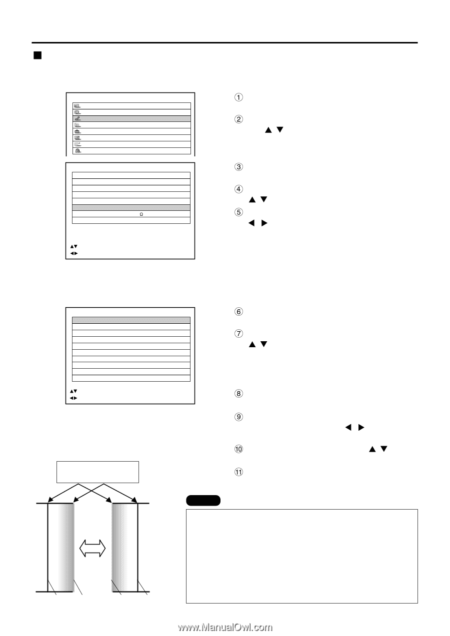
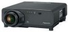
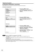
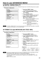
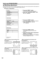
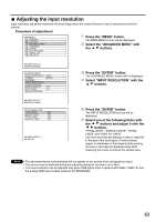
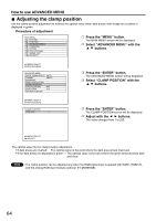
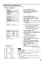
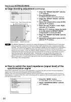
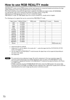
Edge blending adjustment This projector has the function to hide the seams for multi-screens. Procedure of adjustment MAIN MENU PICTURE POSITION ADVANCED MENU LANGUAGE OPTION TEST PATTERN SIGNAL LIST SECURITY Press the "MENU" button. The MAIN MENU screen will be displayed. Select the "ADVANCED MENU" with the buttons. ADVANCED MENU DIGITAL CINEMA REALITY AUTO FORMAT SMPTE BLANKING INPUT RESOLUTION CLAMP POSITION EDGE BLENDING ON SYNC.TERM 75 RASTER POSITION :MENU SELECT :CHANGE ENTER:SUB MENU Press the "ENTER" button. The ADVANCED MENU screen will be displayed. Select "EDGE BLENDING" with the buttons. Select "OFF", "ON" or "USER" with the buttons. OFF: When the multi-screens are not going to be used. ON: When the tilting inside the unit is to be used for the tilting of the edge blending area. USER: When a specific tilting is to be used for the tilting of the edge blending area. (Separate software is required to establish these settings. Consult your dealer.) EDGE BLENDING UPPER OFF LOWER OFF LEFT OFF RIGHT OFF MARKER BRIGHT ADJUST START WIDTH START WIDTH START WIDTH START WIDTH :MENU SELECT :ADJUST ENTER:CHANGE 0 128 0 128 0 128 0 128 OFF The optimal point is where these lines overlap. Red line Green line Green line Red line Press the "ENTER" button. The EDGE BLENDING screen will be displayed. Specify the area to be adjusted with the buttons. To joint the top: set "UPPER" to "ON". To joint the bottom: set "LOWER" to "ON". To joint the left: set "LEFT" to "ON". To joint the right: set "RIGHT" to "ON". Press the "ENTER" button to toggle "ON" and "OFF". Adjust the compensation width and start position with the buttons. Select "MARKER" with the buttons. Select "ON" with the ENTER buttons. Note (Continued on next page) Adjustment marker When the "MARKER" is set to "ON", the image position adjustment marker is displayed. The optimal point is the position where the red line of one frame overlaps the green line of the other frame. Notice: The correction widths of the jointed frames must be the same value all the time. The optimal joint cannot be achieved if the jointed frames have different correction widths. 65
-
 1
1 -
2
-
3
-
4
-
5
-
6
-
7
-
8
-
9
-
10
-
11
-
12
-
13
-
14
-
15
-
16
-
17
-
18
-
19
-
20
-
21
-
22
-
23
-
24
-
25
-
26
-
27
-
28
-
29
-
30
-
31
-
32
-
33
-
34
-
35
-
36
-
37
-
38
-
39
-
40
-
41
-
42
-
43
-
44
-
45
-
46
-
47
-
48
-
49
-
50
-
51
-
52
-
53
-
54
-
55
-
56
-
57
-
58
-
59
-
 60
60 -
 61
61 -
 62
62 -
 63
63 -
 64
64 -
 65
65 -
 66
66 -
 67
67 -
 68
68 -
 69
69 -
 70
70 -
71
-
72
-
73
-
74
-
75
-
76
-
77
-
78
-
79
-
80
-
81
-
82
-
83
-
84
-
85
-
86
-
87
-
88
-
89
-
90
-
91
-
92
-
93
-
94
-
95
-
96
-
97
-
98
-
99
-
100
-
101
-
102
-
103
-
104
-
105
-
106
-
107
-
108
-
109
-
110
-
111
-
112
-
113
-
114
-
115
-
116
 |
 |