Pioneer 4350HD Owner's Manual - Page 61
Connecting control cords
 |
UPC - 012563010815
View all Pioneer 4350HD manuals
Add to My Manuals
Save this manual to your list of manuals |
Page 61 highlights
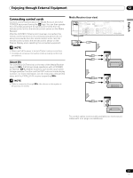
Enjoying through External Equipment 12 English Connecting control cords Connect control cords between the Media Receiver and other PIONEER equipment having the logo. You can then operate the connected equipment by sending commands from its remote control unit to the remote control sensor on the Media Receiver. After the CONTROL IN terminals have been connected, the remote control sensors on the connected equipment do not accept commands from the remote control units. Face the remote control units to the remote control sensor on the Plasma Display when operating the connected equipment. Media Receiver (rear view) IN OUT VCR CONTROL CONTROL IN ANTENNA B ANTENNA/ CABLE A IN Cable CARD S-VIDEO INPUT 2 VIDEO R-AUDIO-L DIGITAL OUT OPTICAL (TS) S400 VIDEO INPUT 1 COMPONENT VIDEO R-AUDIO-L Y CB/PB CR/PR SERVICE ONLY OUT MONITOR OUT S-VIDEO VIDEO R-AUDIO-L S-VIDEO R-AUDIO-L IINNPUTT 33 Y CB/PB CR/PR INPUT 1 INPUT 3 HDMI IN OUT CONTROL • Make sure that the power is turned off when making connections. • Complete all component connections before making control cord connections. About SR+ The CONTROL OUT terminal on the rear of the Media Receiver supports SR+ that allows linked operations with a PIONEER AV receiver. SR+ presents functions such as the input switch linkage operation function and the DSP surround mode display function. For more information, see the instruction manual that came with the PIONEER AV receiver supporting SR+. • While in connection through SR+, the volume on this system is temporarily minimized. CONTROL IN OUT CONTROL IN OUT CONTROL IN OUT The control cables (commercially available) are mono sound cables with mini plugs (no resistance). 61 En
-
 1
1 -
2
-
3
-
4
-
5
-
6
-
7
-
8
-
9
-
10
-
11
-
12
-
13
-
14
-
15
-
16
-
17
-
18
-
19
-
20
-
21
-
22
-
23
-
24
-
25
-
26
-
27
-
28
-
29
-
30
-
31
-
32
-
33
-
34
-
35
-
36
-
37
-
38
-
39
-
40
-
41
-
42
-
43
-
44
-
45
-
46
-
47
-
48
-
49
-
50
-
51
-
52
-
53
-
54
-
55
-
 56
56 -
 57
57 -
 58
58 -
 59
59 -
 60
60 -
 61
61 -
 62
62 -
 63
63 -
 64
64 -
 65
65 -
 66
66 -
67
-
68
-
69
-
70
-
71
-
72
-
73
-
74
-
75
-
76
-
77
-
78
-
79
-
80
-
81
-
82
-
83
-
84
-
85
-
86
-
87
-
88
-
89
-
90
-
91
-
92
-
93
-
94
-
95
-
96
-
97
-
98
-
99
-
100
-
101
-
102
-
103
-
104
-
105
-
106
-
107
-
108
-
109
-
110
-
111
-
112
-
113
-
114
-
115
-
116
-
117
-
118
-
119
-
120
-
121
-
122
-
123
-
124
-
125
-
126
-
127
-
128
-
129
-
130
-
131
-
132
-
133
-
134
-
135
-
136
-
137
-
138
-
139
-
140
-
141
-
142
-
143
-
144
-
145
-
146
-
147
-
148
-
149
-
150
-
151
-
152
-
153
-
154
-
155
-
156
-
157
-
158
-
159
-
160
-
161
-
162
-
163
-
164
-
165
-
166
-
167
-
168
-
169
-
170
-
171
-
172
-
173
-
174
-
175
-
176
-
177
-
178
-
179
-
180
-
181
-
182
-
183
-
184
-
185
-
186
-
187
-
188
-
189
-
190
-
191
-
192
-
193
-
194
-
195
-
196
-
197
-
198
-
199
-
200
-
201
-
202
-
203
-
204
-
205
-
206
-
207
-
208
-
209
-
210
-
211
-
212
-
213
-
214
-
215
-
216
-
217
-
218
-
219
-
220
-
221
-
222
-
223
-
224
-
225
 |
 |
