Pioneer PRO-1000HD Owner's Manual - Page 11
AUDIO INPUT3 RCA Pin jacks - speakers
 |
View all Pioneer PRO-1000HD manuals
Add to My Manuals
Save this manual to your list of manuals |
Page 11 highlights
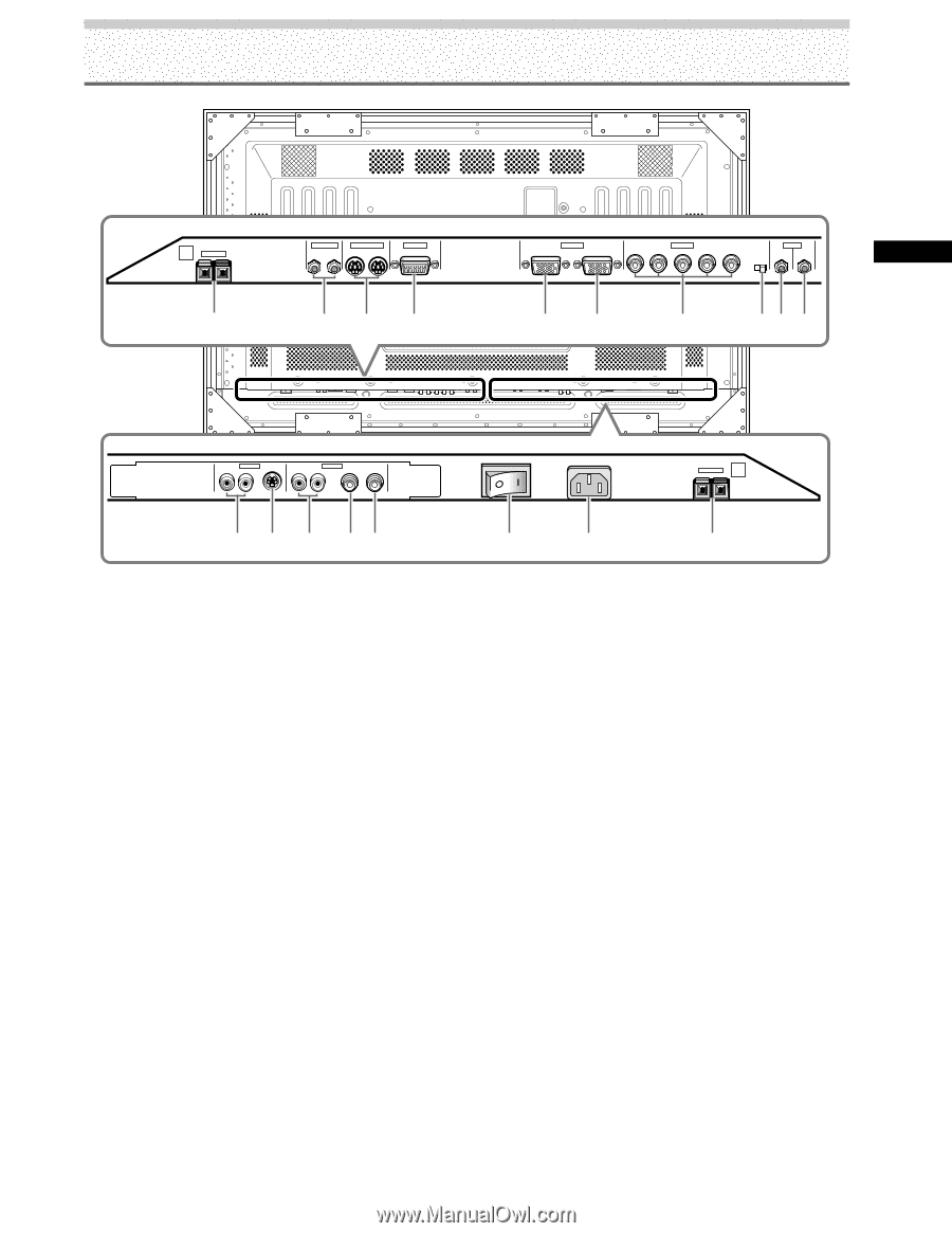
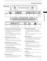
Illustration depicts PRO-1000HD model. R 8Ω ~16Ω S+PEAKE-R 1 CONTROL IN OUT COMBINATION IN OUT RS-232C 23 4 Part Names and Functions INPUT1 (ON SYNC) ANALOG RGB OUTPUT (ANALOG RGB) G B INPUT2 (H/V SYNC) R HD VD 7Ω5Ô2k.Ω2 AUDIO INPUT OUTPUT (INPUT1/2) 56 7 89 0 Part Names and Functions AUDIO INPUT3 S-VIDEO R L AUDIO R INPUT4 VIDEO L OUTPUT AC INLET 8Ω ~16Ω SPEAKER + - L - = ~ !@ 8 Synchronizing signal impedance selector switch Depending on the connections made at INPUT2, it may be necessary to set this switch to match the output impedance of the connected component's synchronization signal. When the output impedance of the component's synchronization signal is below 75 Ω, set this switch to the 75 Ω position (pages 10, 12). 9 AUDIO INPUT (Stereo mini jack) Use to obtain sound when INPUT1 or INPUT2 is selected. Connect the audio output terminal of components connected to INPUT1 or INPUT2 to this unit (page 14). 0 AUDIO OUTPUT (Stereo mini jack) Use to output the audio of the selected source component connected to this unit to an AV amplifier or similar component (page 14). - AUDIO INPUT3 (RCA Pin jacks) Use to obtain sound when INPUT3 is selected. Connect these jacks to the audio output connectors of components connected to INPUT3 (page 14). Note: The left audio channel (L) jack is not compatible with monaural input sources. = INPUT3 (S-video jack) For connection of components that have an S-video output terminal such as a video deck, video camera, LaserDisc player, or DVD player. (page 13) # $ % ~ AUDIO INPUT4 (RCA Pin jacks) Use to obtain sound when INPUT4 is selected. Connect these terminals to the audio output connectors of components connected to INPUT4 (page 15). Note: The left audio channel (L) jack is not compatible with monaural input sources. ! INPUT4 (BNC jack) For connection of components that have a composite video output terminal such as a video deck, video camera, LaserDisc player, or DVD player (page 13). @ OUTPUT (INPUT4) (BNC jack) Use the OUTPUT (INPUT4) terminal to output the video signal to an external monitor or other component. Note: The video signal will not be output from the OUTPUT (INPUT4) terminal when the main power of this display is off or in standby mode (page 13). # Main power switch Use to switch the main power of the unit on and off. $ AC INLET Use to connect the supplied power cord to an AC outlet (page 16). % SPEAKER (L) terminal For connection of an external left speaker. Connect a speaker that has an impedance of 8 -16 Ω (page 14). 7 PRO-1000HD / PRO-800HD
-
 1
1 -
2
-
3
-
4
-
5
-
 6
6 -
 7
7 -
 8
8 -
 9
9 -
 10
10 -
 11
11 -
 12
12 -
 13
13 -
 14
14 -
 15
15 -
 16
16 -
17
-
18
-
19
-
20
-
21
-
22
-
23
-
24
-
25
-
26
-
27
-
28
-
29
-
30
-
31
-
32
-
33
-
34
-
35
-
36
-
37
-
38
-
39
-
40
-
41
-
42
-
43
-
44
 |
 |