Pioneer PRO-1000HD Owner's Manual - Page 15
Connection to a personal, computer
 |
View all Pioneer PRO-1000HD manuals
Add to My Manuals
Save this manual to your list of manuals |
Page 15 highlights
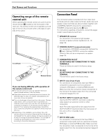
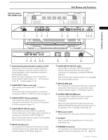
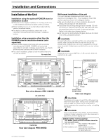
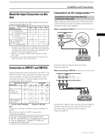
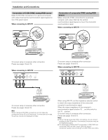
Installation and Connections Connection to a personal computer Connection method differs depending on the computer type. When connecting, please thoroughly read the computer's instruction manual. Before making connections, be sure to make sure that the personal computer's power and this unit's main power is off. For the PC input signals and screen sizes that this unit is compatible with, please refer to supplement 1 (pages 37 to 38). Connection of separate SYNC analog RGB source Make separate SYNC connections for a personal computer that has RGB output separated into 5 output signals: green, blue, red, horizontal synchronization signal, and vertical synchronization signal. When connecting to INPUT2 (ON SYNC) G B INPUT2 (H/V SYNC) R HD VD 7Ω5Ô2k.Ω2 Installation and Connections When connecting to INPUT1 INPUT1 OUTPUT ANALOG RGB (ANALOG RGB) Connect the cable corresponding to the shape of the input terminal on this unit and the personal computer's output terminal. Secure by tightening the terminal screws on both units. After connecting, on-screen setup is necessary. Please see pages 18 and 19. Note Depending on the type of computer model being connected, a conversion connector or adapter etc. provided with the computer or sold separately may be necessary. For details, please read your PC's instruction manual or consult the maker or nearest dealer of your computer. When connecting to OUTPUT (INPUT1) INPUT1 OUTPUT ANALOG RGB (ANALOG RGB) When using INPUT2, set the impedance selector switch to match the output impedance of the connected computer's synchronization signal. When the output impedance of the computer's synchronization signal is below 75 Ω, set this switch to the 75 Ω position. On-screen setup is necessary after connection. Please see pages 18 and 19. To an external monitor With this unit, it is possible to output the video signal to an external monitor or other component from the OUTPUT (INPUT1) terminal. Note A video signal will not be output from the OUTPUT (INPUT1) terminal when the main power of this unit is off or in standby. 11 PRO-1000HD / PRO-800HD
-
 1
1 -
2
-
3
-
4
-
5
-
6
-
7
-
8
-
9
-
 10
10 -
 11
11 -
 12
12 -
 13
13 -
 14
14 -
 15
15 -
 16
16 -
 17
17 -
 18
18 -
 19
19 -
 20
20 -
21
-
22
-
23
-
24
-
25
-
26
-
27
-
28
-
29
-
30
-
31
-
32
-
33
-
34
-
35
-
36
-
37
-
38
-
39
-
40
-
41
-
42
-
43
-
44
 |
 |
