Pioneer PRO-1000HD Owner's Manual - Page 43
Explanation of Terms, Supplement 3, Supplement 2 - tv
 |
View all Pioneer PRO-1000HD manuals
Add to My Manuals
Save this manual to your list of manuals |
Page 43 highlights
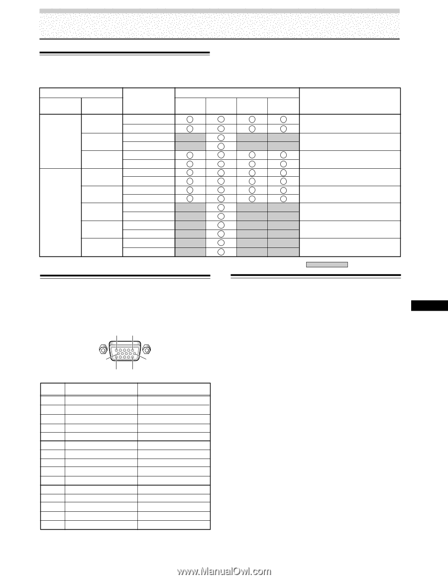
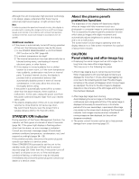
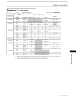
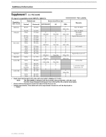
Additional Information Supplement 2 Video signal compatibilty table (INPUT1, INPUT2) Refresh rate Vertical FV (Hz) Horizontal FH (kHz) Signal format 4:3 15.625 Component RGB 50 Component 28.1 RGB 31.25 Component RGB 15.734 Component RGB Component 31.5 RGB 60 33.75 Component RGB Component 45.0 RGB Component 67.5 RGB Screen size FULL ZOOM WIDE Remarks 575i / SDTV 1080i / HDTV 575p / SDTV 480i / SDTV 480p / SDTV 1080i / HDTV 720p / HDTV 1080p / HDTV : Not available. Supplement 3 Signal assignment of INPUT 1 (Mini D-sub 15 pin socket connector) 51 10 6 15 11 Pin No. Input 1 R or CR/PR 2 G or Y 3 B or CB/PB 4 NC (No connection) 5 GND 6 GND 7 GND 8 GND 9 DDC + 5V 10 GND 11 NC (No connection) 12 DDC SDA 13 HD or H/V SYNC 14 VD 15 DDC SCL Output NC (No connection) + + NC (No connection) + + NC (No connection) Explanation of Terms Aspect ratio The TV screen's width to height ratio is referred to as its aspect ratio. The aspect ratio on standard TVs is 4:3 and on wide TVs or High Definition TVs it is 16:9. S jack (S VIDEO jack) This jack separates and transmits the video signal as two signals; the luminance (Y) signal and the color(C) signal. Because of this, picture reproduction is superior to that obtained at the composite input/output jacks. S-video signal The video signal is composed of two signals; the chroma signal (color signal) which reproduces color and the luminance signal which reproduces light and darkness. With standard video components, these two signals are combined into one and are handled as a video signal referred to as the "composite signal". The S-video signal, however, is a signal that handles these two signals separately. Because they are not combined as in the composite video signal, the high quality of both signals can be retained. Component video signal General term for video signal format composed of the Y.CB.CR, Y.PB.PR and Y.B-Y.R-Y luminance signal + color signal. The component video signal is sometimes simply called the "color difference signal". G ON SYNC This indicates a video signal in the form of a synchronization signal added to the G (GREEN) signal of the R.G.B signal. VGA VGA is short for "Video Graphics Array". Generally this indicates a 640 dot x 480 line resolution. XGA General term for "eXtended Graphics Array". Generally this indicates a 1024 dot x 768 line resolution. 39 PRO-1000HD / PRO-800HD Additional Information
-
 1
1 -
2
-
3
-
4
-
5
-
6
-
7
-
8
-
9
-
10
-
11
-
12
-
13
-
14
-
15
-
16
-
17
-
18
-
19
-
20
-
21
-
22
-
23
-
24
-
25
-
26
-
27
-
28
-
29
-
30
-
31
-
32
-
33
-
34
-
35
-
36
-
37
-
 38
38 -
 39
39 -
 40
40 -
 41
41 -
 42
42 -
 43
43 -
 44
44
 |
 |