Pioneer PRO-1000HD Owner's Manual - Page 19
Control Cord Connection
 |
View all Pioneer PRO-1000HD manuals
Add to My Manuals
Save this manual to your list of manuals |
Page 19 highlights
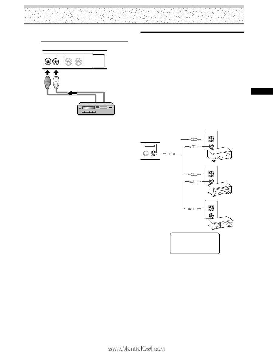
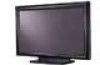
Installation and Connections Audio connection for component connected to INPUT4 AUDIO R INPUT4 VIDEO L OUTPUT Audio input to the AUDIO INPUT4 terminals (pin jacks (L/ R)) is possible for a component connected to INPUT4. Sound is output from both the AUDIO OUTPUT terminal (stereo mini jack (L/R)) and the SPEAKER terminals according to the video input selection. Installation and Connections Control Cord Connection When control cord connections are made, remote control operation of connected PIONEER components that bear the Î logo mark is done through the remote sensor on this unit. When the connection is made to the CONTROL IN terminal on another unit, the remote sensor of that component will no longer receive signals. Point the remote control unit of the connected component at the remote control sensor on this unit to control. Notes ÷ Make sure the power is turned off when making connections. ÷ Please complete all component connections before making control cord connections. Main unit CONTROL IN OUT CONTROL IN OUT CONTROL IN OUT CONTROL IN OUT The control cables (not supplied) are monaural cables with mini plugs (no resistance). 15 PRO-1000HD / PRO-800HD
-
 1
1 -
2
-
3
-
4
-
5
-
6
-
7
-
8
-
9
-
10
-
11
-
12
-
13
-
 14
14 -
 15
15 -
 16
16 -
 17
17 -
 18
18 -
 19
19 -
 20
20 -
 21
21 -
 22
22 -
 23
23 -
 24
24 -
25
-
26
-
27
-
28
-
29
-
30
-
31
-
32
-
33
-
34
-
35
-
36
-
37
-
38
-
39
-
40
-
41
-
42
-
43
-
44
 |
 |