Poulan PP4218A Instruction Manual - Page 7
Assembly - clutch drum
 |
View all Poulan PP4218A manuals
Add to My Manuals
Save this manual to your list of manuals |
Page 7 highlights
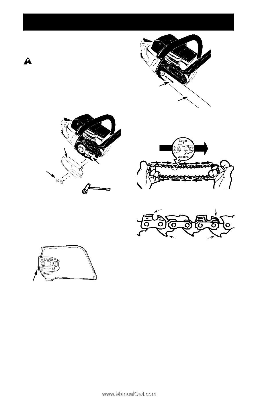
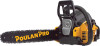
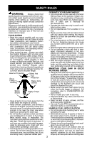
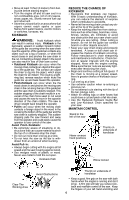
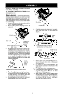
ASSEMBLY Protective gloves (not provided) should be worn during assembly. ATTACHING THE BAR & CHAIN (If not already attached) WARNING: If received assembled, repeat all steps to ensure your saw is properly assembled and all fasteners are secure. Always wear gloves when handling the chain. The chain is sharp and can cut you even when it is not moving! 1. Loosen and remove the bar nuts and the clutch cover from the saw. 2. Remove the plastic shipping spacer (if present). Bar bolts Guide bar 6. Carefully remove the chain from the package. Hold chain with the drive links as shown. Clutch cover Tip of Bar Bar nuts Location of shipping spacer Chain adjustment tool (Bar Tool) 3. An adjusting pin and screw is used to adjust the tension of the chain. It is very important when assembling the bar, that the pin located on the adjusting screw aligns into a hole in the bar. Turning the screw will move the adjustment pin up and down the screw. Locate this adjustment before you begin mounting the bar onto the saw. See following illustration. Inside view of clutch cover Adjustment located on clutch cover 4. Turn the adjusting screw by hand counterclockwise until the adjusting pin just touches the stop. This should allow the pin to be near the correct position. 5. Slide guide bar on bar bolts until guide bar stops against clutch drum sprocket. CUTTERS MUST FACE IN DIIRECTION OF ROTATION Cutters Depth Gauge Drive Links 7. Place chain over and behind clutch retainer, fitting the drive links in the clutch drum sprocket. 8. Fit bottom of drive links between the teeth in the sprocket in the nose of the guide bar. 9. Fit chain drive links into bar groove. 10. Pull guide bar forward until chain is snug in guide bar groove. Ensure all drive links are in the bar groove. 11. Now, install clutch cover making sure the adjusting pin is positioned in the lower hole in the guide bar. Remember this pin moves the bar forward and backward as the screw is turned. 7
-
 1
1 -
 2
2 -
 3
3 -
 4
4 -
 5
5 -
 6
6 -
 7
7 -
 8
8 -
 9
9 -
 10
10 -
 11
11 -
 12
12 -
13
-
14
-
15
-
16
-
17
-
18
-
19
-
20
-
21
-
22
-
23
-
24
-
25
-
26
-
27
-
28
-
29
-
30
-
31
-
32
-
33
-
34
-
35
-
36
-
37
-
38
-
39
-
40
-
41
-
42
-
43
-
44
-
45
-
46
-
47
-
48
-
49
-
50
-
51
-
52
-
53
-
54
-
55
-
56
-
57
-
58
-
59
-
60
-
61
-
62
-
63
-
64
-
65
-
66
-
67
-
68
 |
 |