ProForm C840 Bench English Manual - Page 10
Assemble the Left Spotter Hook 54 and
 |
View all ProForm C840 Bench manuals
Add to My Manuals
Save this manual to your list of manuals |
Page 10 highlights
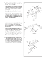
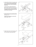
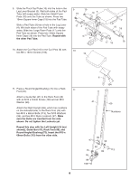
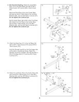
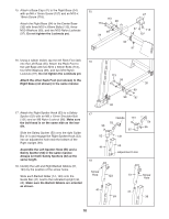
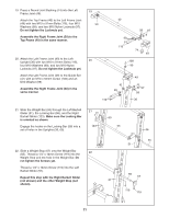
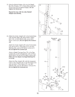
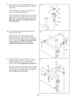
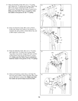
15. Attach a Base Cap (47) to the Right Base (34) with an M4 x 16mm Screw (107) and an M10 x 19mm Screw (118). Attach the Right Base (34) to the Center Base (32) with three M10 x 68mm Bolts (113), three M10 Washers (99), and two M10 Nylon Locknuts (97). Do not tighten the Locknuts yet. 15 113 99 113 99 34 47 97 118 107 32 97 16. Using a rubber mallet, tap the left Rack Foot (46) into the Left Base (35). Attach the Rack Foot to the Left Base with two M10 x 68mm Bolts (113), four M10 Washers (99), and two M10 Nylon Locknuts (97). Do not tighten the Locknuts yet. Attach the other Rack Foot (not shown) to the Right Base (not shown) in the same manner. 17. Attach the Right Spotter Hook (53) to a Safety Spotter (52) with an M8 x 12mm Shoulder Bolt (131) and an M8 Nylon Locknut (96). Make sure the bolt head is on the same side as the handle. Slide the Safety Spotter (52) onto the right Guide Bar (41) and engage the Right Spotter Hook (53) into an adjustment hole near the bottom of the Right Upright (69). Assemble the Left Spotter Hook (54) and a Safety Spotter (52) in the same manner. Always set both Safety Spotters (52) at the same height. 18. Identify the Left and Right Barbell Gliders (51, 123) by the position of the screw holes. Slide each Barbell Glider (51, 123) onto the Guide Bar (41) next to the indicated Upright (36, 69). Make sure the Barbell Gliders are oriented as shown. 16 113 99 35 99 99 97 46 17 Handle 131 53 96 52 52 131 54 96 41 18 69 Adjustment Hole Screw Hole 123 51 Screw Hole 41 41 69 36 10
-
 1
1 -
2
-
3
-
4
-
 5
5 -
 6
6 -
 7
7 -
 8
8 -
 9
9 -
 10
10 -
 11
11 -
 12
12 -
 13
13 -
 14
14 -
 15
15 -
16
-
17
-
18
-
19
-
20
-
21
-
22
-
23
-
24
-
25
-
26
-
27
-
28
-
29
-
30
-
31
-
32
-
33
 |
 |
