ProForm C840 Bench English Manual - Page 6
Attach the Leg Lever 4 to the Leg Lever Bracket - press
 |
View all ProForm C840 Bench manuals
Add to My Manuals
Save this manual to your list of manuals |
Page 6 highlights
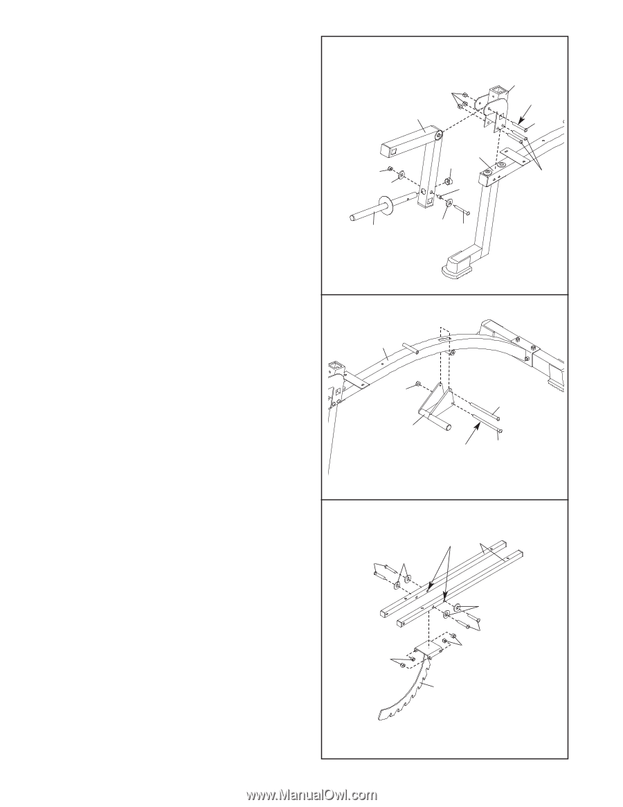
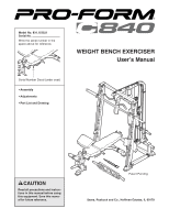
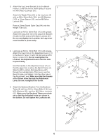
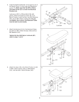
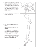
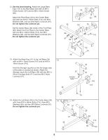
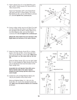
3. Attach the Leg Lever Bracket (5) to the Bench 3 Frame (1) with two M10 x 68mm Bolts (113) and two M10 Nylon Locknuts (97). Attach the Weight Tube (25) to the Leg Lever (4) with an M8 x 58mm Bolt (106), two M8 Washers (100), a 10mm Spacer (30), and an M8 Nylon Locknut (96). Press a 25mm Round Outer Cap (94) onto the Weight Tube (25). Lubricate an M10 x 68mm Bolt (113) with grease. Attach the Leg Lever (4) to the Leg Lever Bracket (5) with the Bolt and an M10 Nylon Locknut (97). Do not overtighten the Locknut; the Leg Lever must be able to pivot easily. 97 4 96 100 1 94 30 25 100 106 5 Lubricate 113 113 4. Lubricate an M10 x 78mm Bolt (110) with grease. 4 Attach the lower hole in the Adjustment Lever (11) to the Bench Frame (1) with the Bolt and an M10 Nylon Locknut (97). Do not overtighten the Locknut; the Adjustment Lever must be able to pivot easily. Hold the handle on the Adjustment Lever (11) so that the upper hole is above the Bench Frame (1). Slide the M10 x 62mm Flat Head Screw (27) through the indicated side of the Lever, over the Bench Frame, and tighten it into the other side of the Adjustment Lever. Make sure that the threads of the Screw show through the Adjustment Lever. Do not overtighten the Screw. 1 97 11 27 Lubricate 110 5. Attach the Backrest Bracket (7) to the Backrest 5 Tubes (8) with four M10 x 45mm Bolts (112), four M10 Washers (99), and four M10 Nylon Locknuts (97). Make sure the Backrest Tubes are orient- Holes 8 ed so that the indicated holes are closer to the bottom. Do not tighten the Locknuts yet. 112 99 99 112 97 97 7 6
-
 1
1 -
 2
2 -
 3
3 -
 4
4 -
 5
5 -
 6
6 -
 7
7 -
 8
8 -
 9
9 -
 10
10 -
 11
11 -
 12
12 -
13
-
14
-
15
-
16
-
17
-
18
-
19
-
20
-
21
-
22
-
23
-
24
-
25
-
26
-
27
-
28
-
29
-
30
-
31
-
32
-
33
 |
 |