ProForm C840 Bench English Manual - Page 9
Set the Center Base 32 inside of the Foot Plate
 |
View all ProForm C840 Bench manuals
Add to My Manuals
Save this manual to your list of manuals |
Page 9 highlights
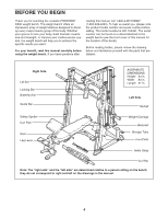
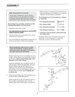
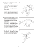
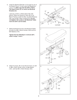
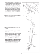
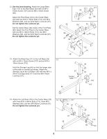
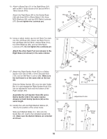
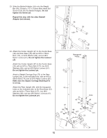
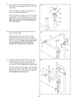
12. See the inset drawing. Attach the Large Base 12 Cap (117) to the Rear Base (33) with an M4 x 16mm Screw (107) and an M8 x 16mm Screw (98). 117 33 Attach the Rear Base (33) to the Center Base (32) with two M10 x 78mm Bolts (110), two M10 Washers (99), and two M10 Nylon Locknuts (97). Do not tighten the Locknuts yet. 98 107 32 110 33 Set the Center Base (32) inside of the Foot Plate (48). Attach the Foot Plate to the Center Base with two M10 x 68mm Bolts (113), two M10 99 Washers (99), and two M10 Nylon Locknuts (97). 110 Do not tighten the Locknuts yet. 97 99 97 99 113 13. Attach the Base Cap (47) to the Left Base (35) 13 with an M4 x 16mm Screw (107) and an M10 x 19mm Screw (118). Hold the Storage Leg (45) so that the longer side of the plate is oriented as shown. Attach the Storage Leg to the Left Base (35) with two M10 x 92mm Carriage Bolts (111) and two M10 Nylon Locknuts (97). 48 97 Longer Side 35 45 97 47 118 107 14. Attach the Left Base (35) to the Center Base (32) 14 with three M10 x 68mm Bolts (113), three M10 Washers (99), and two M10 Nylon Locknuts (97). Do not tighten the Locknuts yet. 111 32 97 97 35 9 99 113 99 113
-
 1
1 -
2
-
3
-
 4
4 -
 5
5 -
 6
6 -
 7
7 -
 8
8 -
 9
9 -
 10
10 -
 11
11 -
 12
12 -
 13
13 -
 14
14 -
15
-
16
-
17
-
18
-
19
-
20
-
21
-
22
-
23
-
24
-
25
-
26
-
27
-
28
-
29
-
30
-
31
-
32
-
33
 |
 |
