ProForm C840 Bench English Manual - Page 12
Make sure the Square Carriage Bushing 61
 |
View all ProForm C840 Bench manuals
Add to My Manuals
Save this manual to your list of manuals |
Page 12 highlights
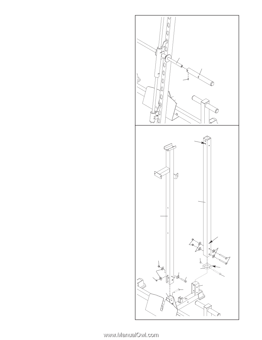
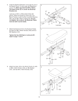
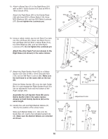
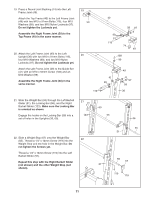
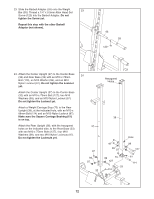
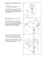
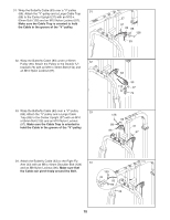
23. Slide the Barbell Adapter (59) onto the Weight 23 Bar (55). Thread a 1/4" x 9.5mm Allen Head Set Screw (120) into the Barbell Adapter. Do not tighten the Screw yet. Repeat this step with the other Barbell Adapter (not shown). 55 59 120 24. Attach the Center Upright (37) to the Center Base (32) and Rear Base (33) with an M10 x 78mm Bolt (110), an M10 Washer (99), and an M10 Nylon Locknut (97). Do not tighten the Locknut yet. Attach the Center Upright (37) to the Center Base (32) with an M10 x 75mm Bolt (127), two M10 Washers (99), and an M10 Nylon Locknut (97). Do not tighten the Locknut yet. Attach a Weight Carriage Stop (70) to the Rear Upright (38), at the indicated hole, with an M10 x 88mm Bolt (114) and an M10 Nylon Locknut (97). Make sure the Square Carriage Bushing (61) is on top. Attach the Rear Upright (38), with the hexagonal holes on the indicated side, to the Rear Base (33) with two M10 x 75mm Bolts (127), four M10 Washers (99), and two M10 Nylon Locknuts (97). Do not tighten the Locknuts yet. 24 37 97 99 97 32 Hexagonal Holes 38 97 99 97 99 70 127 33 110 Hole 99 127 61 114 12
-
 1
1 -
2
-
3
-
4
-
5
-
6
-
 7
7 -
 8
8 -
 9
9 -
 10
10 -
 11
11 -
 12
12 -
 13
13 -
 14
14 -
 15
15 -
 16
16 -
 17
17 -
18
-
19
-
20
-
21
-
22
-
23
-
24
-
25
-
26
-
27
-
28
-
29
-
30
-
31
-
32
-
33
 |
 |