RCA DRC8052N User Guide - Page 15
Connection: DVD recorder + TV + Satellite Receiver - users guide
 |
UPC - 840356939995
View all RCA DRC8052N manuals
Add to My Manuals
Save this manual to your list of manuals |
Page 15 highlights
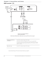
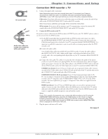
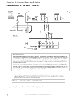
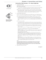
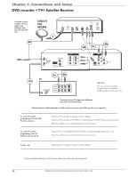
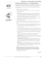
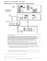
RF Coaxial cable Red Yellow White Audio video cables are usually color-coded red, white, and yellow. Chapter 1: Connections and Setup Connection: DVD recorder + TV + Satellite Receiver The following instructions enable you to record the programs from your satellite receiver. Because the jack configuration and labels vary on different satellite receivers and televisions, the steps provided are general guidelines. Consult your satellite receiver and/or television user's guides for additional information. 1. Satellite signal: Leave the cable in place that comes from the satellite dish and goes to the satellite receiver. 2. Connect the satellite receiver to the DVD recorder 2a. Connect a coaxial cable to the satellite receiver's OUT TO TV jack, and to the ANTENNA/ CABLE INPUT jack on the DVD recorder. 2b. Connect audio cables (red and white) to the satellite receiver's output jacks [sometimes labeled Audio Left (white) and Audio Right (red)]. Connect the other ends of these cables to the corresponding AV1 INPUT AUDIO L and AUDIO R jacks on the back of the DVD recorder. 2c. Connect the video cable (yellow) to the Video Output jack on the satellite receiver (sometimes labeled VIDEO) to the INPUT VIDEO jack on the back of the DVD recorder. 2d. If your satellite receiver, has an S-VIDEO OUT jack, connect an S-Video cable to that jack and to the S-VIDEO IN jack on the DVD recorder for improved picture quality. 3. Connect the DVD recorder to the TV You need to connect cables from the DVD recorder's OUTPUT jacks to the TV's INPUT jacks in order to see the content from the DVD recorder (whether it's a satellite program or a disc you're playing). 3a. Connect an RF coaxial cable to the DVD recorder's ANTENNA/CABLE OUTPUT jack and to the TV's Antenna Input jack (sometimes labeled CABLE/ANTENNA). It is important to make this connection so you can watch satellite programs when the DVD recorder is off. 3b. Connect the audio cables. A set of audio/video cables was packed with your DVD recorder. Connect the audio cables to the AUDIO OUTPUT L (left - white) and R (right - red) jacks on the back of your DVD recorder, and to the corresponding Audio Input jacks on your TV (sometimes labeled AUDIO IN L and R). 3c. Connect the video cable. The cables you use for the video determine the quality of the picture you'll see on your TV when you're playing DVDs. For more information about cables and signal quality, go to page 5. Connect the video cable (yellow) to the VIDEO OUTPUT jack on the back of your DVD recorder, and to the Video Input jack on your TV (sometimes labeled VIDEO IN). S-VIDEO (not shown) If your TV has an S-VIDEO input jack, connect one end of an optional SVideo cable to the S-VIDEO input jack on the back of the TV and the other end to the S-VIDEO OUT jack on the back of the DVD recorder. COMPONENT VIDEO Y, Pb, Pr (not shown) If your TV has Component Input Jacks (Y, Pb, Pr), you can achieve even greater picture quality (DVD playback only) by connecting the DVD recorder to the TV using these jacks (COMPONENT VIDEO OUT, Y, Pb, Pr on the DVD recorder). For more explanation, go to page 5. Component Video cables not supplied with the DVD recorder. HDMI (not shown) If you TV has an HDMI Input Jack, you can achieve optimum picture quality. Connect one end of the HDMI cable to the HDMI jack on the back of the TV and the other end to the HDMI jack on the back of the DVD recorder. Press the HDMI button on the remote to toggle the available progressive scan and interlace modes. Notes: If your TV is capable of progressive scan, connect the DVD recorder to the TV using the COMPONENT VIDEO OUT jacks, and press the HDMI button on the remote to toggle between progressive scan and interlace. Please note that the component video output mode will remain at 480p even though the HDMI video output mode is 480p/720p/1080i, which is displayed on the front of the unit. 4. Plug the power cord into an AC outlet. Go to page 17 Graphics contained within this publication are for representation only. 13
-
 1
1 -
2
-
3
-
4
-
5
-
6
-
7
-
8
-
9
-
 10
10 -
 11
11 -
 12
12 -
 13
13 -
 14
14 -
 15
15 -
 16
16 -
 17
17 -
 18
18 -
 19
19 -
 20
20 -
21
-
22
-
23
-
24
-
25
-
26
-
27
-
28
-
29
-
30
-
31
-
32
-
33
-
34
-
35
-
36
-
37
-
38
-
39
-
40
-
41
-
42
-
43
-
44
-
45
-
46
 |
 |