RCA DRC8052N User Guide - Page 8
Back of the DVD Recorder - dvd recorder with hdmi
 |
UPC - 840356939995
View all RCA DRC8052N manuals
Add to My Manuals
Save this manual to your list of manuals |
Page 8 highlights
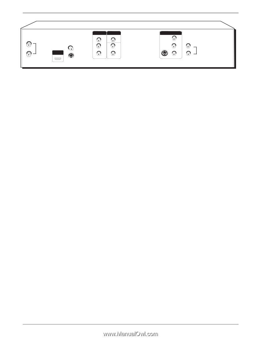
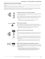
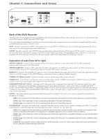
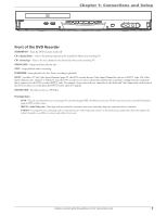
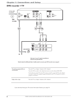
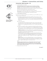
Chapter 1: Connections and Setup IN ANTENNA /CABLE OUT COAXIAL OUT HDMI OUT S-VIDEO OUT COMPONENT VIDEO OUT Y Pb Pr OUTPUT VIDEO L AUDIO R AV1 IN VIDEO IN L R S-VIDEO IN L AUDIO IN R Back of the DVD Recorder The back of your recorder might look a little overwhelming at first. This section explains what goes where and why. There are two sets of jacks on the back of your DVD recorder-INPUT jacks and OUTPUT jacks. Each jack is explained individually below, but the basic idea is about sending and receiving information to be played on or through your DVD recorder and displaying that information on your TV screen. INPUT The cables connected to the INPUT jacks bring pictures and sound INTO the DVD recorder, such as the cable signal (programming) from the cable company or satellite programming from a satellite receiver. OUTPUT The cables connected to the OUTPUT jacks are sending pictures and sound from the DVD recorder OUT TO your TV so you can see it on the screen. The correct cables must be connected to the DVD recorder's Output jacks and the corresponding Input Jacks on the TV so you can see the program on the TV. You must also tune the TV to the correct channel, called a Video Input Channel (for details, go to page 20). Explanation of Jacks (from left to right) ANTENNA /CABLE IN - Connect an RF coaxial cable from an off-air antenna, cable box, or cable outlet to this jack. The cable is sending the programming from the source to the DVD recorder. ANTENNA/CABLE OUT - Connect an RF coaxial cable (provided) to this jack and to the Cable/Antenna Input jack on your TV. It is important to connect this cable so that your TV receives programming even when the DVD recorder is turned off. HDMI OUT - If your TV has an HDMI jack, connects to your TV for high-definition video signal. Also provides 2-channel audio signal when the audio output is set to PCM. See page 34. Press the HDMI button on the remote control to toggle the available resolutions. COAXIAL OUT (Digital Coaxial) - Connects to an audio receiver or decoder using a digital coaxial connection. S-VIDEO OUT - If your TV has an S-Video jack, connect an S-Video cable to the TV's S-VIDEO jack and to this S-VIDEO OUT jack on the DVD recorder to achieve better picture quality than standard video (the yellow jack). COMPONENT VIDEO OUT (Y, Pb, Pr) - Some high-end TVs and monitors have Component Video Input jacks. The cables that send the video signal through these Output jacks provide the highest resolution because the video signal is divided into 3 separate parts (cables not supplied with DVD recorder). As with VIDEO and S-VIDEO, COMPONENT VIDEO (Y, Pb, Pr) only carries the picture signal so you need to connect the audio cables so you'll hear the sound. If your TV has COMPONENT INPUT jacks, use three video grade cables to connect the DVD recorder to these jacks on the TV to get the best picture quality. OUTPUT - These jacks send the content (audio and video) from your DVD recorder OUT to the TV so you can see it on the TV screen and hear it through the TV's speakers. VIDEO: Color coded yellow, the video cable you use with this jack provides better quality than an RF coaxial cable but isn't as good as S-Video. AUDIO L (left): Color coded white, connect corresponding audio cable to TV's Audio Left Input jack. AUDIO R (right): Color coded red, connect corresponding audio cable to TV's Audio Right Input jack. AV1 IN/AUDIO IN - These jacks receive audio from a compatible component, such as a satellite receiver. Another set of Input Jacks (INPUT 2) are on the front of the DVD recorder for temporarily connecting components such as a camcorder or a video game unit. VIDEO: Color coded yellow, the video cable you use with this jack provides better quality than an RF coaxial cable but isn't as good as S-Video. Connect corresponding video cable to the output jack of a compatible component, such as a satellite receiver or cable box. AUDIO L (left): Color coded white, connect corresponding audio cable to the output jack of a compatible component, such as a satellite receiver or cable box. AUDIO R (right): Color coded red, connect corresponding audio cable to the output jack of a compatible component, such as a satellite receiver or cable box. S-VIDEO IN: If your satellite receiver or cable box has an S-VIDEO output jack, connect the S-Video cable to this jack because it provides better picture quality than standard video (the yellow jack). continues on next page... 6 Graphics contained within this publication are for representation only.
-
 1
1 -
2
-
 3
3 -
 4
4 -
 5
5 -
 6
6 -
 7
7 -
 8
8 -
 9
9 -
 10
10 -
 11
11 -
 12
12 -
 13
13 -
14
-
15
-
16
-
17
-
18
-
19
-
20
-
21
-
22
-
23
-
24
-
25
-
26
-
27
-
28
-
29
-
30
-
31
-
32
-
33
-
34
-
35
-
36
-
37
-
38
-
39
-
40
-
41
-
42
-
43
-
44
-
45
-
46
 |
 |