Ricoh P C600 User Guide - Page 19
Interior: Front view, Replenishing and Replacing Consumables.
 |
View all Ricoh P C600 manuals
Add to My Manuals
Save this manual to your list of manuals |
Page 19 highlights
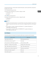
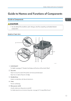
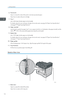
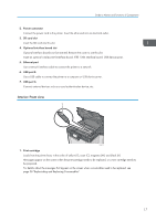
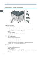
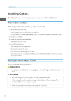
Guide to Names and Functions of Components 2. Power connector Connect the power cord to the printer. Insert the other end into an electrical outlet. 3. SD card slot Insert the SD card into this slot. 4. Optional interface board slot Optional interface boards can be inserted. Remove the cover to use this slot. Insert an optional wireless LAN interface board, IEEE 1284 interface board, USB device server. 5. Ethernet port Use a network interface cable to connect the printer to a network. 6. USB port B Use a USB cable to connect the printer to a computer or USB device server. 7. USB port A Connect external devices such as a card authentication device, etc. Interior: Front view 1 EAG337 1. Print cartridge Loads from the printer front, in the order of yellow (Y), cyan (C), magenta (M), and black (K). Messages appear on the screen when the print cartridge needs to be replaced, or a new cartridge needs to be prepared. For details about the messages that appear on the screen when consumables need to be replaced, see page 38 "Replenishing and Replacing Consumables". 17
-
 1
1 -
2
-
3
-
4
-
5
-
6
-
7
-
8
-
9
-
10
-
11
-
12
-
13
-
 14
14 -
 15
15 -
 16
16 -
 17
17 -
 18
18 -
 19
19 -
 20
20 -
 21
21 -
 22
22 -
 23
23 -
 24
24 -
25
-
26
-
27
-
28
-
29
-
30
-
31
-
32
-
33
-
34
-
35
-
36
-
37
-
38
-
39
-
40
-
41
-
42
-
43
-
44
-
45
-
46
-
47
-
48
-
49
-
50
-
51
-
52
-
53
-
54
-
55
-
56
-
57
-
58
-
59
-
60
-
61
-
62
-
63
-
64
-
65
-
66
-
67
-
68
-
69
-
70
-
71
-
72
-
73
-
74
-
75
-
76
-
77
-
78
-
79
-
80
-
81
-
82
-
83
-
84
-
85
-
86
-
87
-
88
-
89
-
90
-
91
-
92
-
93
-
94
-
95
-
96
-
97
-
98
-
99
-
100
-
101
-
102
-
103
-
104
-
105
-
106
-
107
-
108
-
109
-
110
-
111
-
112
-
113
-
114
-
115
-
116
-
117
-
118
-
119
-
120
-
121
-
122
-
123
-
124
-
125
-
126
-
127
-
128
 |
 |