Ricoh P C600 User Guide - Page 33
Installing the USB device server, Procedure for installing the USB device server
 |
View all Ricoh P C600 manuals
Add to My Manuals
Save this manual to your list of manuals |
Page 33 highlights
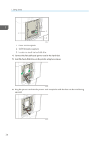
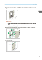
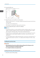
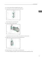
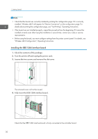
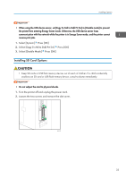
5. Tighten the two screws to secure the interface board. Installing Options EAG342 6. Plug in the power cord, and then turn on the printer. 7. Print the configuration page to confirm that the board was attached correctly. • Check that the board was correctly installed by printing the configuration page. If it is correctly installed, "Parallel Interface" will appear for "Device Connection" on the configuration page. For details about printing the configuration page, see "Test Printing", Operating Instructions. • If the board was not installed properly, repeat the procedure from the beginning. If it cannot be installed correctly even after trying the installation a second time, contact your sales or service representative. Installing the USB device server The USB device server is an interface board that adds an Ethernet port to the printer. With this device installed, two Ethernet cables can be connected at the same time using the standard port on the printer and an additional port on the USB device server. You can assign different IP addresses to each port, so the printer can print jobs from different network segments. Procedure for installing the USB device server 1. Check the contents of the package. 2. Turn the printer off and unplug the power cord. 31
-
 1
1 -
2
-
3
-
4
-
5
-
6
-
7
-
8
-
9
-
10
-
11
-
12
-
13
-
14
-
15
-
16
-
17
-
18
-
19
-
20
-
21
-
22
-
23
-
24
-
25
-
26
-
27
-
 28
28 -
 29
29 -
 30
30 -
 31
31 -
 32
32 -
 33
33 -
 34
34 -
 35
35 -
 36
36 -
 37
37 -
 38
38 -
39
-
40
-
41
-
42
-
43
-
44
-
45
-
46
-
47
-
48
-
49
-
50
-
51
-
52
-
53
-
54
-
55
-
56
-
57
-
58
-
59
-
60
-
61
-
62
-
63
-
64
-
65
-
66
-
67
-
68
-
69
-
70
-
71
-
72
-
73
-
74
-
75
-
76
-
77
-
78
-
79
-
80
-
81
-
82
-
83
-
84
-
85
-
86
-
87
-
88
-
89
-
90
-
91
-
92
-
93
-
94
-
95
-
96
-
97
-
98
-
99
-
100
-
101
-
102
-
103
-
104
-
105
-
106
-
107
-
108
-
109
-
110
-
111
-
112
-
113
-
114
-
115
-
116
-
117
-
118
-
119
-
120
-
121
-
122
-
123
-
124
-
125
-
126
-
127
-
128
 |
 |
