Ridgid CA-100 Owners Manual - Page 7
FCC Statement, Electromagnetic, Compatibility EMC, Tool Assembly - extension
 |
View all Ridgid CA-100 manuals
Add to My Manuals
Save this manual to your list of manuals |
Page 7 highlights
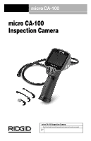
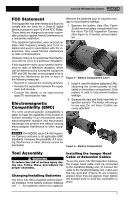
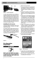
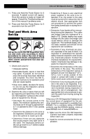
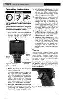
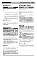
micro CA-100 Inspection Camera FCC Statement This equipment has been tested and found to comply with the limits for a Class B digital device, pursuant to part 15 of the FCC Rules. These limits are designed to provide reasonable protection against harmful interference in a residential installation. This equipment generates, uses, and can radiate radio frequency energy and, if not installed and used in accordance with the instructions, may cause harmful interference to radio communications. However, there is no guarantee that interference will not occur in a particular installation. If this equipment does cause harmful interference to radio or television reception, which can be determined by turning the equipment OFF and ON, the user is encouraged to try to correct the interference by one or more of the following measures: • Reorient or relocate the receiving antenna. • Increase the separation between the equip- ment and receiver. • Consult the dealer or an experienced radio/TV technician for help. Electromagnetic Compatibility (EMC) The term electromagnetic compatibility is taken to mean the capability of the product to function smoothly in an environment where electromagnetic radiation and electrostatic discharges are present and without causing electromagnet interference to other equipment. NOTICE The RIDGID micro CA-100 Inspection Camera conforms to all applicable EMC standards. However, the possibility of it causing interference in other devices cannot be precluded. Remove the batteries prior to long term storage to avoid battery leakage. 1. Squeeze the battery clips (See Figure 3) and remove battery compartment from the micro CA-100 Inspection Camera (See Figure 4). If needed, remove batteries. Figure 3 - Battery Compartment Cover 2. Install 4 new AA alkaline batteries (LR6), observing the correct polarity as indicated on the battery compartment. Only replace in sets to help prevent battery leakage. 3. Squeeze the clips and firmly insert into inspection camera. The holder will only go in one way. Do not force. Confirm securely attached. Figure 4 - Battery Compartment Tool Assembly WARNING To reduce the risk of serious injury during use, follow these procedures for proper assembly. Changing/Installing Batteries The micro CA-100 is supplied without batteries installed. If the battery indicator displays red , the batteries need to be replaced. Installing the Imager Head Cable or Extension Cables To use the micro CA-100 Inspection Camera, the imager head cable must be connected to the handheld display unit. To connect the cable to the handheld display unit, make sure the key and slot (Figure 5) are properly aligned. Once they are aligned, finger tighten the knurled knob to hold the connection in place. 5
-
 1
1 -
 2
2 -
 3
3 -
 4
4 -
 5
5 -
 6
6 -
 7
7 -
 8
8 -
 9
9 -
 10
10 -
 11
11 -
 12
12 -
13
-
14
-
15
-
16
-
17
-
18
-
19
-
20
-
21
-
22
-
23
-
24
-
25
-
26
-
27
-
28
-
29
-
30
-
31
-
32
-
33
-
34
-
35
-
36
-
37
-
38
-
39
-
40
-
41
-
42
-
43
-
44
-
45
-
46
-
47
-
48
-
49
-
50
-
51
-
52
-
53
-
54
-
55
-
56
-
57
-
58
-
59
-
60
-
61
-
62
-
63
-
64
 |
 |
