Ridgid CA-100 Owners Manual - Page 8
Pre-Operation, Inspection - form
 |
View all Ridgid CA-100 manuals
Add to My Manuals
Save this manual to your list of manuals |
Page 8 highlights
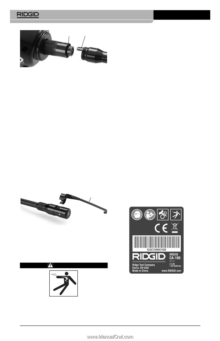
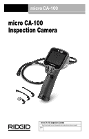
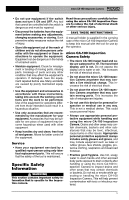
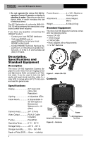
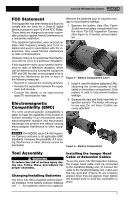
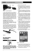
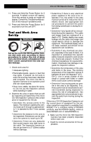
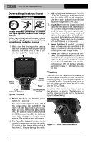
micro CA-100 Inspection Camera Slot Key Figure 5 - Cable Connections 3' and 6' cable extensions are available to increase the length of your cable up to 30' in length. To install an extension, first remove the camera head cable from the display unit by loosening the knurled knob. Connect the extension to the handheld as described above (Figure 5). Connect the keyed end of the camera head cable to the slotted end of the extension and finger tighten the knurled knob to hold the connection in place. Installing An Accessory The three included accessories, (mirror, hook and magnet) (Figure 1) all attach to the imager head the same way. To connect, hold the imager head as shown in Figure 6. Slip the semicircle end of the accessory over the flats of the imager head as shown in Figure 6. Then rotate the accessory a 1/4 turn so the long arm of the accessory is extending out as shown (Figure 6). Accessory 1. Make sure the unit is OFF. 2. Remove the battery holder and inspect it and batteries for signs of damage. Replace batteries if necessary. Do not use inspection camera if batteries are damaged. 3. Clean any oil, grease or dirt from the equipment. This aids inspection and helps prevent the tool from slipping from your grip. 4. Inspect micro CA-100 Inspection Camera for any broken, warn, missing, misaligned or binding parts or any condition which may prevent safe and normal operation. 5. Inspect the camera head lens for condensation. To avoid damaging the unit, do not use the camera if condensation forms inside the lens. Let the water evaporate before using. 6. Inspect the full length of the cable for cracks or damage. A damaged cable could allow water to enter the unit and increase the risk of electrical shock. 7. Check to make sure the connections between the handheld unit, extension cables and imager cable are tight. All connections must be properly assembled for the cable to be water resistant. Confirm unit is properly assembled. 8. Check that the warning label is present, firmly attached and readable. Figure 6 Pre-Operation Inspection WARNING Figure 7 - Warning Label Before each use, inspect your inspection camera and correct any problems to reduce the risk of serious injury from electric shock and other causes and prevent tool damage. 9. If any issues are found during the inspection, do not use the inspection camera until it has been properly serviced. 10. With dry hands, re-install the battery holder making sure to fully insert. 6
-
 1
1 -
2
-
 3
3 -
 4
4 -
 5
5 -
 6
6 -
 7
7 -
 8
8 -
 9
9 -
 10
10 -
 11
11 -
 12
12 -
 13
13 -
14
-
15
-
16
-
17
-
18
-
19
-
20
-
21
-
22
-
23
-
24
-
25
-
26
-
27
-
28
-
29
-
30
-
31
-
32
-
33
-
34
-
35
-
36
-
37
-
38
-
39
-
40
-
41
-
42
-
43
-
44
-
45
-
46
-
47
-
48
-
49
-
50
-
51
-
52
-
53
-
54
-
55
-
56
-
57
-
58
-
59
-
60
-
61
-
62
-
63
-
64
 |
 |