Ridgid KJ-3100 Owners Manual - Page 7
Machine Assembly - water jetter manual
 |
View all Ridgid KJ-3100 manuals
Add to My Manuals
Save this manual to your list of manuals |
Page 7 highlights
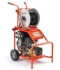
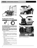
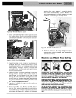
KJ-2200/KJ-3100 Water Jetting Machines Icons Pressure Mode Pulse Mode Standard Equipment All Jetters come with • Appropriate Jetter Nozzles • Nozzle Cleaning Tool • FV-1 Foot Valve • Engine Operator's Manual See the RIDGID catalog for specific equipment supplied with each catalog number. NOTICE This machine is made to clean drains. If properly used it will not damage a drain that is in good condition and properly designed, constructed and maintained. If the drain is in poor condition or not properly designed, constructed or maintained, the drain cleaning process may not be effective or could cause damage to the drain. The best way to determine the condition of a drain before cleaning is through visual inspection with a camera. Improper use of this jetting machine can damage the jetter and the drain. This machine may not clear all blockages. Machine Assembly WARNING To prevent serious injury during use and prevent machine damage, follow these procedures for proper assembly. Engine Oil NOTICE Jetter is shipped without oil in the engine. Operating the engine without oil will result in engine failure. Add oil prior to operation. See supplied engine operator's manual for specific information on adding oil and oil selection. Pump/Gearbox Oil Pump: Replace the plug in the top of the pump and replace with dipstick/breather cap. Operating the jetter with the plug in place could damage the pump seals. Check oil level per Maintenance Instruction section. Gearbox (KJ-3100 only): Replace the plug in the top of the pump with dipstick/breather cap. Operating the jetter with the plug in place could damage the gearbox seals. Check lubricant level per the Maintenance Instruction section. Outer Grove Retaining Clip Figure 4 - Assembly of the KJ-2200 KJ-2200 Transport Cart 1. Install retaining clip into inner groove on each end of axle. (See Figure 4.) 2. Slide a wheel over each end of axle. 3. Install retaining clip into outer groove on each end of axle to retain wheel. 4. Use the supplied carriage bolts and wing nuts to at- tach the handle to the frame. 5. Lift the motor/pump assembly onto the cart, aligning the holes in the base plate with the pins in the top of the cart. Use the latches on the cart to retain the motor/pump. Make sure the assembly is securely attached. KJ-3100 Handle Assembly 1. Insert handle through the two holes in the rear cross bar of the frame. (See Figure 5.) 2. Insert a hairpin through the holes at the bottom of the handle to prevent the handle from pulling out. 3. Screw the T-knobs into the rear cross bar. Adjust the handles as desired and tighten the knobs to secure the handle. 5
-
 1
1 -
 2
2 -
 3
3 -
 4
4 -
 5
5 -
 6
6 -
 7
7 -
 8
8 -
 9
9 -
 10
10 -
 11
11 -
 12
12 -
13
-
14
-
15
-
16
-
17
-
18
-
19
-
20
-
21
-
22
-
23
-
24
-
25
-
26
-
27
-
28
-
29
-
30
-
31
-
32
-
33
-
34
-
35
-
36
-
37
-
38
-
39
-
40
-
41
-
42
-
43
-
44
-
45
-
46
-
47
-
48
-
49
-
50
-
51
-
52
-
53
-
54
-
55
-
56
-
57
-
58
-
59
-
60
 |
 |
