Ridgid R4331 Operation Manual - Page 11
Assembly - thickness planer
 |
View all Ridgid R4331 manuals
Add to My Manuals
Save this manual to your list of manuals |
Page 11 highlights
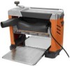
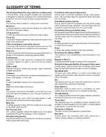
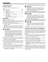
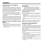
ASSEMBLY LOOSE PARTS LIST See Figure 5, page 22. The following items are included with the tool: Key No. A B C D E F Description Qty. Dust guide 1 Magnetic blade wrench 1 Switch key 1 Depth adjustment crank handle 1 Lock washer 1 Hex head screw 1 Operator's Manual (not shown 1 UNPACKING This product requires assembly. Note: Every RIDGID® Thickness Planer is tested at the factory to insure its performance. You may see small amounts of wood dust and chips on your new planer. Carefully lift the tool from the carton and place it on a level work surface. NOTE: This tool is heavy. To avoid back injury, lift with your legs, not your back, and get help when needed. WARNING: Do not use this product if any parts on the Loose Parts List are already assembled to your product when you unpack it. Parts on this list are not assembled to the product by the manufacturer and require customer installation. Use of a product that may have been improperly assembled could result in serious personal injury. Inspect the tool carefully to make sure no breakage or damage occurred during shipping. Do not discard the packing material until you have carefully inspected and satisfactorily operated the product. Remove the plastic covering the planer table prior to turning on this product. The saw is factory set for accurate cutting. After assembling it, check for accuracy. If shipping has influenced the settings, take to an authorized service center. If any parts are damaged or missing, please call 1-866-539-1710 for assistance. Warning: If any parts are damaged or missing do not operate this product until the parts are replaced. Use of this product with damaged or missing parts could result in serious personal injury. WARNING: Do not attempt to modify this tool or create accessories not recommended for use with this tool. Any such alteration or modification is misuse and could result in a hazardous condition leading to possible serious personal injury. WARNING: Do not connect to power supply until assembly is complete. Failure to comply could result in accidental starting and possible serious personal injury. MOUNTING the PLANER to workbench If your planer is to be used in a permanent location, it is recommended you secure it to a workbench or other stable surface. When mounting the planer to a workbench, holes should be drilled through the supporting surface of the workbench. Mark holes on workbench where planer is to be mounted using holes in planer base as a template for hole pattern. Drill four holes through workbench. Place planer on workbench aligning holes in the planer base with holes drilled in the workbench. Insert four bolts (not included) and tighten securely with lock washers and hex nuts (not included). Note: All bolts should be inserted from the top. Install the lock washers and hex nuts from the underside of the workbench. Supporting surface where planer is mounted should be examined carefully after mounting to insure that no movement during use can result. If any tipping or walking is noted, secure workbench or support surface before beginning planing operation. 11
-
 1
1 -
2
-
3
-
4
-
5
-
 6
6 -
 7
7 -
 8
8 -
 9
9 -
 10
10 -
 11
11 -
 12
12 -
 13
13 -
 14
14 -
 15
15 -
 16
16 -
17
-
18
-
19
-
20
-
21
-
22
-
23
-
24
-
25
-
26
-
27
-
28
-
29
-
30
-
31
-
32
-
33
-
34
-
35
-
36
-
37
-
38
-
39
-
40
-
41
-
42
-
43
-
44
-
45
-
46
-
47
-
48
-
49
-
50
-
51
-
52
-
53
-
54
-
55
-
56
-
57
-
58
-
59
-
60
-
61
-
62
-
63
-
64
 |
 |
