Ridgid R4331 Operation Manual - Page 18
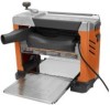
Note: S Illustrations Start On After, French And Spanish Language S. - ridge planer
 |
View all Ridgid R4331 manuals
Add to My Manuals
Save this manual to your list of manuals |
Page 18 highlights
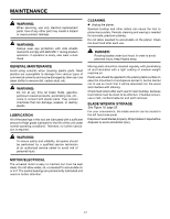
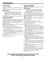
MAINTENANCE Cord storage See Figure 19, page 25. When not in use, the power cord should be wrapped around the planer. CAUTION: Check extension cords before each use. If damaged, replace immediately. Never use tool with a damaged cord since touching the damaged area could cause electrical shock resulting in serious injury. BRUSH REPLACEMENT See Figure 20, page 26. Externally accessible brush assemblies are located at the right front and the left rear of the planer. These brushes should be inspected every 10 to 15 operating hours for wear. Replace both brushes when either brush has less than 1/4 in. of carbon remaining. NOTE: The dust hood may be removed for easier access when removing the rear brush cap. Unplug planer and remove the switch key. Using a flat-head screwdriver, unscrew the brush cap. The brush assembly is spring-loaded and will pop out when you remove the cap. Remove the brush assembly (brush and spring) and inspect for wear. If less than 1/4 in. of carbon remains on brush, replace both brush assemblies. Never replace one side without replacing the other. Install new brush assembly, if required, or reinstall old brush assembly. Replace cap and tighten to secure. BLADE REPLACEMENT See Figures 21 - 25, page 26. WARNING: Always wear heavy leather gloves and use caution when loosening blade locking screws and handling and/or changing blades. Blades are sharp and can cause serious injury. The planer is equipped with replaceable/disposable doubleedged cutter blades attached to a rotating cutter head. Worn cutter blades will affect cutting accuracy and may produce ridges on the workpiece. NOTE: The replacement blades may appear slightly different than the original blades. Unplug the planer. Lower the cutter head assembly to 1 in. height. From the back of the planer, remove the dust hood screws holding the dust hood in place. Remove the dust hood. If cutter head is not locked, rotate until it locks. Note: Rotating the cutter head is accomplished by turning the dust exhaust fan with your fingers until the cutter head locks in place. The cutter head lock will engage when the head is rotated. Do not operate thickness planer without the dust hood in place or the planer will be damaged. Carefully loosen and remove the blade locking screws. Using the magnetic blade wrench, remove the blade lock bar by placing the blade wrench on blade, lifting slightly, then pulling straight out. Repeat above step to remove the blade. NOTE: If you are changing to the second side of the blade, rotate the blade "end for end" keeping the same flat side down. This correctly positions the blade for reinstallation. Using the magnetic blade wrench, align holes in blade with pins on cutter head and push the installed blade in firmly. Check that the blade edge is parallel to the cutter head slot. Align blade lock bar over the blade then securely retighten the blade locking screws. Push and hold the cutter head lock down and rotate fan slightly to unlock the cutter head. Release cutter head lock and rotate the cutter head to the next lock position to access access the second blade. Repeat the above steps for the third blade. Replace the dust hood. NOTE: FIGURES (ILLUSTRATIONS) START ON PAGE 21 AFTER FRENCH AND SPANISH LANGUAGE SECTIONS. 18
-
 1
1 -
2
-
3
-
4
-
5
-
6
-
7
-
8
-
9
-
10
-
11
-
12
-
 13
13 -
 14
14 -
 15
15 -
 16
16 -
 17
17 -
 18
18 -
 19
19 -
 20
20 -
 21
21 -
 22
22 -
 23
23 -
24
-
25
-
26
-
27
-
28
-
29
-
30
-
31
-
32
-
33
-
34
-
35
-
36
-
37
-
38
-
39
-
40
-
41
-
42
-
43
-
44
-
45
-
46
-
47
-
48
-
49
-
50
-
51
-
52
-
53
-
54
-
55
-
56
-
57
-
58
-
59
-
60
-
61
-
62
-
63
-
64
 |
 |
