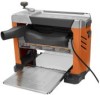
Ridgid R4331 Operation Manual - Page 14
Avoiding Snipe, Warped Wood, Power Switch, Warning, Using Sure-cut, Carriage Lock - weight
 |
View all Ridgid R4331 manuals
Add to My Manuals
Save this manual to your list of manuals |
Page 14 highlights
OPERATION AVOIDING SNIPE Snipe, or depressions made at either end of a workpiece by cutter blades, can occur when the board is not properly supported. Although snipe may be barely noticeable, it is important to keep the workpiece parallel and flat with the planer table to minimize snipe. Butting workpieces endto-end as they are fed through the planer will minimize the problem, especially for shorter pieces, because it provides a more stable feed. For workpieces longer than 48 in., greater care must be taken to reduce the problem because the additional length means more of the total weight is unsupported by the planer table and rollers, causing the shifting weight to work against keeping the stock flat. To remove snipe from a finished workpiece, cut off the end of the workpiece where snipe is noticeable. WARPED WOOD Little or no warpage is the ideal condition for planing a workpiece. Simply turn the workpiece over and plane it to the desired thickness. Otherwise, plane the top first, turn the workpiece and plane the bottom. For a board that is cupped or bowed across its width, the best method is to rip the board lengthwise down the middle and plane the pieces separately. This method eliminates much of the waste in planing cupped or bowed workpieces. The only way to remove the bow from a workpiece that is cupped or bowed down its length is to use a jointer. Avoid using severely warped wood as it can jam the planer. If it must be used, rip it in half before planing to help minimize the possibility of jamming. If jamming does occur, turn the switch off and unplug the planer immediately. Raise the cutter head assembly high enough to remove the workpiece easily. Carefully check to make sure no damage to the tool has occurred before making the next planing pass. Always feed the workpiece in the direction of the grain. This allows the cutter blades to sever the wood fibers instead of tearing them. Feeding against the grain can also cause the cutter blades to chip the workpiece. POWER SWITCH See Figure 11, page 23. The planer is equipped with a power switch that has a built-in locking feature. This feature is intended to prevent unauthorized and possible hazardous use by children and others. TO TURN THE PLANER ON: With the switch key inserted into the switch, lift the switch to turn ON ( l ). TO TURN THE PLANER OFF: With the switch key inserted into the switch, push the switch down to turn OFF ( O ). TO lock THE PLANER: Place the switch in the OFF ( O ) position. Remove the switch key from the switch and store in a secure location. WARNING: Always remove the switch key when the tool is not in use and keep it in a safe place. In the event of a power failure, turn the switch OFF ( O ) and remove the key. This action will prevent the tool from accidentally starting when power returns. WARNING: Always make sure the workpiece is not in contact with the blade before operating the switch to start the tool. Failure to heed this warning could cause the workpiece to be kicked back toward the operator and result in serious personal injury. USING Sure-cut™ carriage lock See Figure 12, page 24. Never adjust the cutter head assembly with the cutter head lock in the "locked" position. A complete rotation of the depth adjustment crank handle moves the cutter head assembly 1/16 in. TO RAISE THE CUTTER HEAD: With the power switch in the OFF ( O ) position, lift the Sure-Cut™ Carriage Lock to unlock the cutter head assembly. Turn the depth adjustment crank handle clockwise to raise the cutter head. Once cutter head is in the desired position, lock the cutter head by pushing the Sure-Cut™ Carriage Lock down. TO LOWER THE CUTTER HEAD: With the power switch in the OFF ( O ) position, lift the Sure-Cut™ Carriage Lock to unlock the cutter head assembly. Turn the depth adjustment crank handle counterclockwise to lower the cutter head. Once cutter head is in the desired position, lock the cutter head by pushing the Sure-Cut™ Carriage Lock down. 14
-
 1
1 -
2
-
3
-
4
-
5
-
6
-
7
-
8
-
 9
9 -
 10
10 -
 11
11 -
 12
12 -
 13
13 -
 14
14 -
 15
15 -
 16
16 -
 17
17 -
 18
18 -
 19
19 -
20
-
21
-
22
-
23
-
24
-
25
-
26
-
27
-
28
-
29
-
30
-
31
-
32
-
33
-
34
-
35
-
36
-
37
-
38
-
39
-
40
-
41
-
42
-
43
-
44
-
45
-
46
-
47
-
48
-
49
-
50
-
51
-
52
-
53
-
54
-
55
-
56
-
57
-
58
-
59
-
60
-
61
-
62
-
63
-
64
 |
 |