Ryobi RTS23 User Manual 5 - Page 12
Operating Components, Switch Assembly, Warning
 |
View all Ryobi RTS23 manuals
Add to My Manuals
Save this manual to your list of manuals |
Page 12 highlights
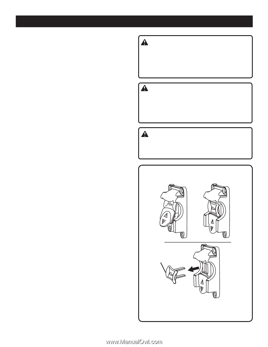
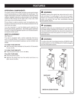
FEATURES OPERATING COMPONENTS The upper portion of the blade projects up through the table and is surrounded by an insert called the throat plate. The height of the blade is set with a handwheel on the front of the cabinet. Detailed instructions are provided in the Operation section of this manual for the basic cuts: cross cuts, miter cuts, bevel cuts, and compound cuts. The rip fence is used to position work for lengthwise cuts. A scale on the front rail shows the distance between the rip fence and the blade. It is very important to use the blade guard assembly for all through-sawing operations. The blade guard assembly includes: riving knife/spreader/splitter, anti-kickback pawls, and plastic blade guard. SWITCH ASSEMBLY See Figure 3. This saw is equipped with a switch assembly that has a built-in locking feature. This feature is intended to prevent unauthorized and possible hazardous use by children and others. TO TURN YOUR SAW ON: With the switch key inserted into the switch, lift the switch to turn on ( l ). TO TURN YOUR SAW OFF: Press the switch down to turn off ( O ). TO LOCK YOUR SAW: Press the switch down. Remove the switch key from the switch and store in a safe, secure location. WARNING: ALWAYS remove the switch key when the tool is not in use and keep it in a safe place. In the event of a power failure, turn the switch off ( O ) and remove the key. This action will prevent the tool from accidentally starting when power returns. WARNING: ALWAYS make sure your workpiece is not in contact with the blade before operating the switch to start the tool. Failure to heed this warning may cause the workpiece to be kicked back toward the operator and result in serious personal injury. WARNING: To reduce the risk of accidental starting, ALWAYS make sure the switch is in the off ( O ) position before plugging tool into the power source. SWITCH ON SWITCH OFF SWITCH KEY SWITCH IN LOCKED POSITION 12 Fig. 3
-
 1
1 -
2
-
3
-
4
-
5
-
6
-
 7
7 -
 8
8 -
 9
9 -
 10
10 -
 11
11 -
 12
12 -
 13
13 -
 14
14 -
 15
15 -
 16
16 -
 17
17 -
18
-
19
-
20
-
21
-
22
-
23
-
24
-
25
-
26
-
27
-
28
-
29
-
30
-
31
-
32
-
33
-
34
-
35
-
36
-
37
-
38
-
39
-
40
-
41
-
42
 |
 |