Ryobi RTS23 User Manual 5 - Page 37
To Set The Blade At 0° And 45°
 |
View all Ryobi RTS23 manuals
Add to My Manuals
Save this manual to your list of manuals |
Page 37 highlights
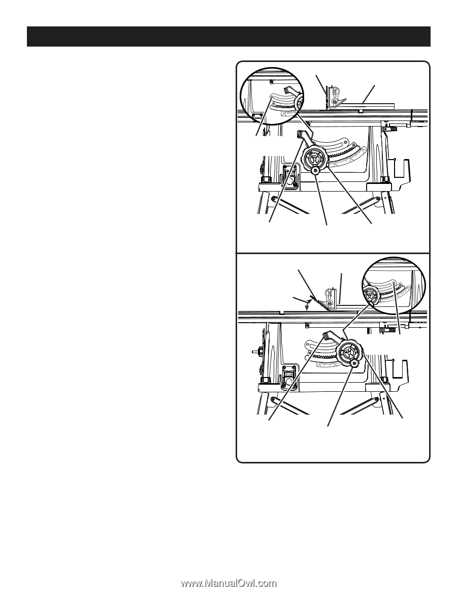
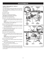
ADJUSTMENTS TO SET THE BLADE AT 0° AND 45° See Figures 53 - 54. The angle settings of the saw have been set at the factory and, unless damaged in shipping, should not require setting during assembly. After extensive use, they may need to be checked. Unplug the saw. Raise the blade. Remove the blade guard assembly. If the blade is not perfectly vertical (0°): Unlock the bevel locking lever. Loosen the 0° adjustment screw. Place a combination square beside the blade on the left. The edge of the square and the saw blade should be parallel. NOTE: Make sure that the square contacts the flat part of the saw blade, not the blade teeth. Lock the bevel locking lever. From under the saw cabinet, hold the screw cam against the bushing. Slightly lift the bevel locking lever to expose the 0° adjustment screw. Tighten the adjustment screw. Check again for squareness and continue to adjust if needed. If the blade is not an exact 45°: Unlock the bevel locking lever. Loosen the 45° adjustment screw. Place a combination square beside the blade on the left. The edge of the square and the saw blade should be parallel. NOTE: Make sure that the square contacts the flat part of the saw blade, not the blade teeth. Lock the bevel locking lever. From under the saw cabinet, hold the screw cam against the bushing. Tighten the adjustment screw. Check again for squareness and continue to adjust if needed. If needed, adjust the bevel indicator to 45°. Make a test cut. The adjustment screws must be below the saw table surface so the workpiece doesn't catch on uneven edges. If unable to make this adjustment, take the product to an authorized service center. BLADE COMBINATION SQUARE 0° ADJUSTMENT SCREW BEVEL LOCKING LEVER HANDLE BEVEL INDICATOR BLADE COMBINATION SQUARE Fig. 53 45° 45° ADJUSTMENT SCREW BEVEL LOCKING LEVER HANDLE BEVEL INDICATOR Fig. 54 37
-
 1
1 -
2
-
3
-
4
-
5
-
6
-
7
-
8
-
9
-
10
-
11
-
12
-
13
-
14
-
15
-
16
-
17
-
18
-
19
-
20
-
21
-
22
-
23
-
24
-
25
-
26
-
27
-
28
-
29
-
30
-
31
-
 32
32 -
 33
33 -
 34
34 -
 35
35 -
 36
36 -
 37
37 -
 38
38 -
 39
39 -
 40
40 -
 41
41 -
 42
42
 |
 |