Ryobi RTS23 User Manual 5 - Page 26
To Change Blade Depth, To Change Blade Angle Bevel, To Adjust The Bevel Indicator
 |
View all Ryobi RTS23 manuals
Add to My Manuals
Save this manual to your list of manuals |
Page 26 highlights
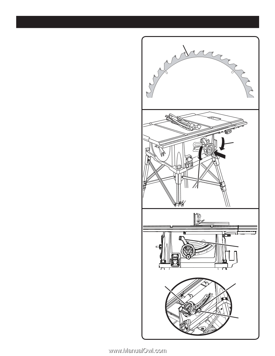
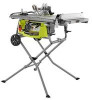
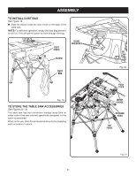
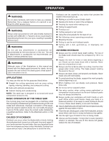
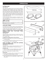
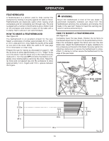
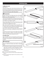
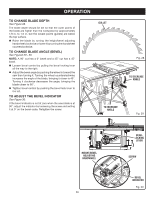
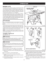
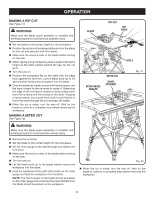
OPERATION TO CHANGE BLADE DEPTH See Figure 28. The blade depth should be set so that the outer points of the blade are higher than the workpiece by approximately 1/8 in. to 1/4 in. but the lowest points (gullets) are below the top surface. Raise the blade by turning the height/bevel adjusting handwheel clockwise or lower it by turning the handwheel counterclockwise. TO CHANGE BLADE ANGLE (BEVEL) See Figured 29 - 30. NOTE: A 90° cut has a 0° bevel and a 45° cut has a 45° bevel. Loosen bevel control by pulling the bevel locking lever all the way to the right. Adjust the bevel angle by pushing the wheel in toward the saw then turning it. Turning the wheel counterclockwise increases the angle of the blade, bringing it closer to 45°. Turning it clockwise decreases the angle, bringing the blade closer to 90°. Tighten bevel control by pushing the bevel lock lever to the left. TO ADJUST THE BEVEL INDICATOR See Figure 30. If the bevel indicator is not at zero when the saw blade is at 90°, adjust the indicator by loosening the screw and setting it at 0° on the bevel scale. Retighten the screw. GULLET TO INCREASE ANGLE Fig. 28 TO DECREASE ANGLE Fig. 29 HEIGHT/BEVEL ADJUSTING HANDWHEEL 26 BEVEL LOCKING LEVER SCREW BEVEL INDICATOR Fig. 30
-
 1
1 -
2
-
3
-
4
-
5
-
6
-
7
-
8
-
9
-
10
-
11
-
12
-
13
-
14
-
15
-
16
-
17
-
18
-
19
-
20
-
 21
21 -
 22
22 -
 23
23 -
 24
24 -
 25
25 -
 26
26 -
 27
27 -
 28
28 -
 29
29 -
 30
30 -
 31
31 -
32
-
33
-
34
-
35
-
36
-
37
-
38
-
39
-
40
-
41
-
42
 |
 |