Ryobi RTS23 User Manual 5 - Page 28
To Use The Miter Gauge, To Use The Miter Gauge In A Reverse, Position, To Use The Sliding Table
 |
View all Ryobi RTS23 manuals
Add to My Manuals
Save this manual to your list of manuals |
Page 28 highlights
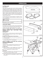
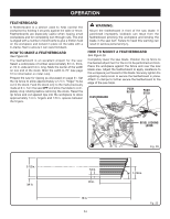
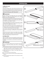
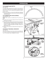
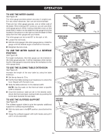
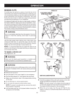
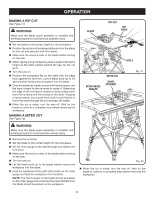
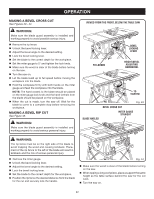
OPERATION TO USE THE MITER GAUGE See Figure 32. The miter gauge provides greater accuracy in angled cuts. For very close tolerances, test cuts are recommended. There are two miter gauge grooves, one on either side of the blade. When making a 90° cross cut, you can use either miter gauge groove. When making a beveled cross cut (the blade tilted in relation to the table) the miter gauge should be located in the groove on the right so that the blade is tilted away from the miter gauge and your hands. The miter gauge can be turned 60° to the right or left. Loosen the lock knob. With the miter gauge in the miter gauge groove, rotate the gauge until the desired angle is reached on the scale. Retighten the lock knob. TO USE THE MITER GAUGE IN A REVERSE POSITION See Figure 33. For larger workpieces, the miter gauge can be reversed in the miter gauge grooves. It will be necessary when reversing the miter gauge to securely clamp the workpiece to the miter gauge body. TO USE THE SLIDING TABLE EXTENSION See Figure 34. Increase the length of the saw table by using the table extension. Set the rip fence to 15 in. Pull the front table locking lever toward you to unlock the lever. Repeat with the back lever. Slide the table extension to the desired width. NOTE: Use the scale on the front rail when a specific width is desired. Once the extension table are set to the desired width, relock the front and back locking levers by pushing the levers back towards the saw base. TO USE THE OUTFEED SUPPORT See Figure 35. The outfeed support slides to give the operator additional support for cutting long workpieces. With the table saw in the OFF position, stand behind the saw. Grasp the outfeed support with both hands and pull it until it is fully extended. MITER GAUGE MITER GAUGE BODY MITER GAUGE REVERSED SLIDING TABLE EXTENSION OUTFEED SUPPORT LOCK KNOB Fig. 32 Fig. 33 TABLE LOCKING LEVER Fig. 34 Fig. 35 28
-
 1
1 -
2
-
3
-
4
-
5
-
6
-
7
-
8
-
9
-
10
-
11
-
12
-
13
-
14
-
15
-
16
-
17
-
18
-
19
-
20
-
21
-
22
-
 23
23 -
 24
24 -
 25
25 -
 26
26 -
 27
27 -
 28
28 -
 29
29 -
 30
30 -
 31
31 -
 32
32 -
 33
33 -
34
-
35
-
36
-
37
-
38
-
39
-
40
-
41
-
42
 |
 |
