Ryobi RTS23 User Manual 5 - Page 20
To Assemble The Sliding Table, Assembly
 |
View all Ryobi RTS23 manuals
Add to My Manuals
Save this manual to your list of manuals |
Page 20 highlights
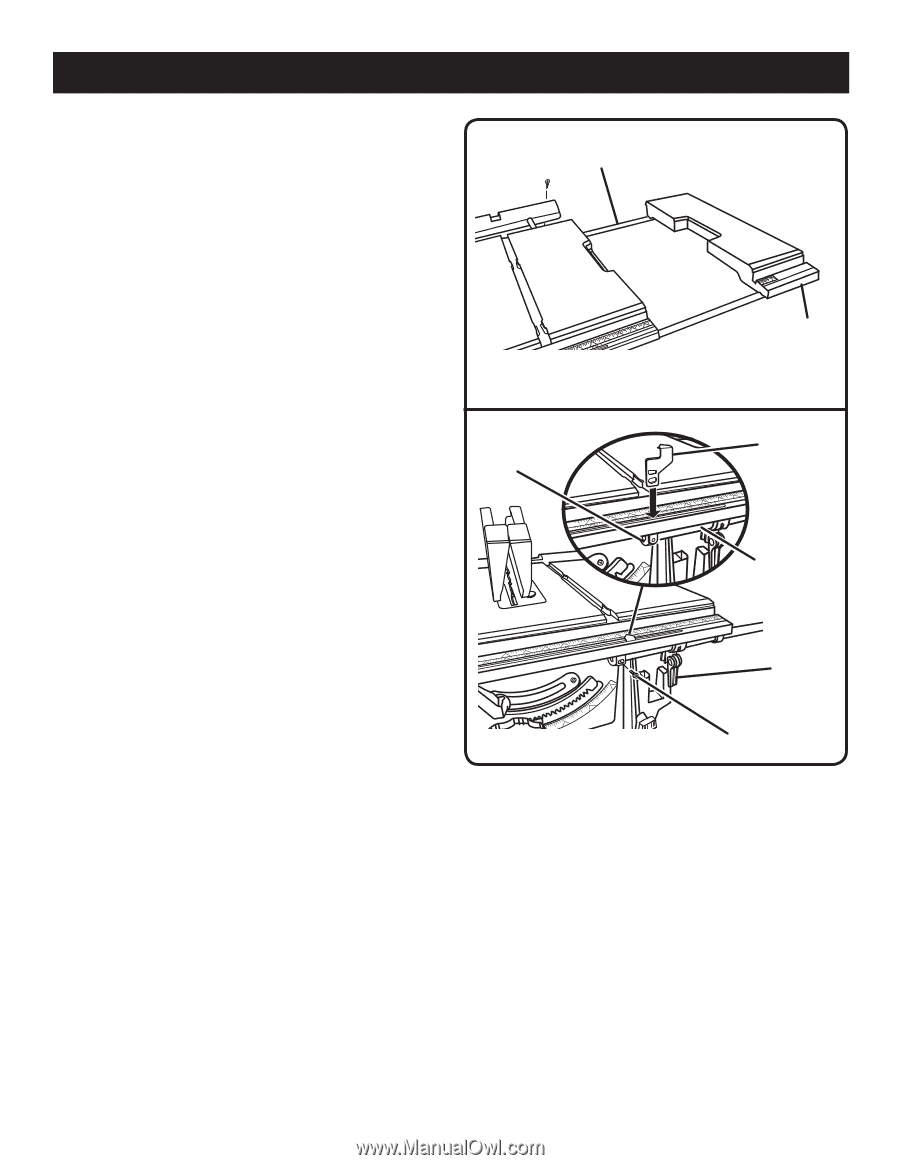
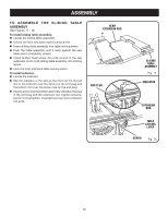
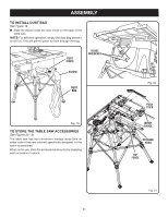
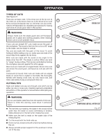
ASSEMBLY TO ASSEMBLE THE SLIDING TABLE ASSEMBLY See Figures 17 - 18. To install sliding table assembly: Locate the sliding table assembly. Unlock the front and back table locking levers. Insert sliding table assembly into table locking levers. Push the table assembly until it rests against the saw table and is completely closed. Install phillips head screw into hole at end of the rear extension rod to hold sliding table assembly into locking levers. Lock the front and back table locking levers. To install indicator: Locate the indicator. Slip the indicator in the slot on the front rail. Fit the top slot in the indicator over the detent on the end plug and the bottom slot over the screw hole on the end plug. Insert a screw into the bottom slot of the indicator, the hole in the end plug and the extension rod. Tighten securely, but do not overtighten. Overtighting may crush extension rod ends. REAR EXTENSION ROD END PLUG SLIDING TABLE ASSEMBLY Fig. 17 INDICATOR EXTENSION ROD TABLE LOCKING LEVER SCREW Fig. 18 20
-
 1
1 -
2
-
3
-
4
-
5
-
6
-
7
-
8
-
9
-
10
-
11
-
12
-
13
-
14
-
 15
15 -
 16
16 -
 17
17 -
 18
18 -
 19
19 -
 20
20 -
 21
21 -
 22
22 -
 23
23 -
 24
24 -
 25
25 -
26
-
27
-
28
-
29
-
30
-
31
-
32
-
33
-
34
-
35
-
36
-
37
-
38
-
39
-
40
-
41
-
42
 |
 |