Samsung SMO-152QN User Guide - Page 31
External terminal connecting method for CAMERA and, MONITOR
 |
UPC - 036725120181
View all Samsung SMO-152QN manuals
Add to My Manuals
Save this manual to your list of manuals |
Page 31 highlights
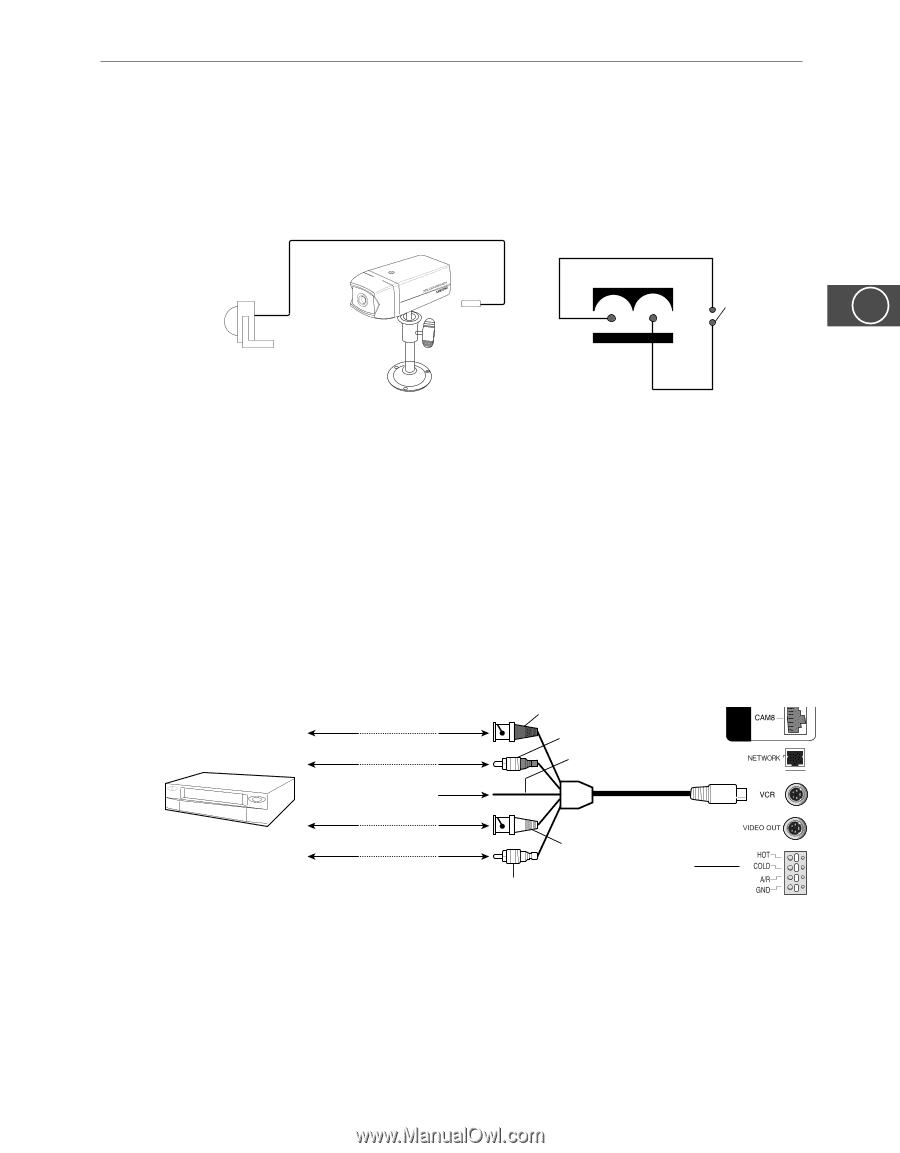
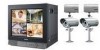
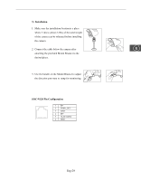
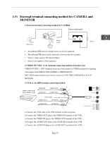
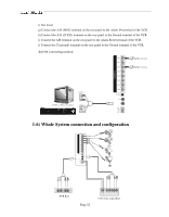
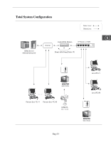
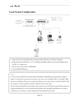
1-5) External terminal connecting method for CAMERA and MONITOR 1) External terminal connecting method for CAMERA Camera alarm injack PIR Sensor Sensor in put E Sensor • An additional PIR sensor or external sensor can also be connected. • The additional PIR sensor can be connected as shown in the above graphic. • Sensor's trigger signal is NO (Normal Open). • Sensor is not supplied. (Sold separately) 2) VIDEO OUT BNC (1~4) terminals connecting method of monitor rear VIDEO OUT BNC1 ~ BNC4 terminals in the rear of the monitor are VIDEO terminals for outputting video images from OBSEVATION CAMERA to THROUGH OUT. BNC VIDEO output terminal can be used to connect to VCR (TIME LAPSE)/DVR or SLAVE MONITOR. 3) VCR or ALARM terminal connecting method TIME LAPSE VCR OR NORMAL VCR VIDEO IN AUDIO IN VIDEO OUT AUDIO OUT b d f NOT USED VIDEO OUT VIDEO IN AUDIO OUT AUDIO IN c a e a) Connect the VCR cable to the VCR terminal on the rear panel. b) Connect the VIDEO OUT plug to the VIDEO IN terminal of the VCR. c) Connect the VIDEO IN plug to the VIDEO OUT terminal of the VCR. d) Connect the AUDIO OUT plug to the AUDIO IN terminal of the VCR. e) Connect the AUDIO IN plug to the AUDIO OUT terminal of the VCR. Eng-31
-
 1
1 -
2
-
3
-
4
-
5
-
6
-
7
-
8
-
9
-
10
-
11
-
12
-
13
-
14
-
15
-
16
-
17
-
18
-
19
-
20
-
21
-
22
-
23
-
24
-
25
-
 26
26 -
 27
27 -
 28
28 -
 29
29 -
 30
30 -
 31
31 -
 32
32 -
 33
33 -
 34
34 -
 35
35 -
 36
36 -
37
-
38
-
39
-
40
-
41
-
42
-
43
-
44
-
45
-
46
-
47
-
48
-
49
-
50
-
51
-
52
-
53
-
54
-
55
-
56
-
57
-
58
-
59
-
60
-
61
-
62
-
63
-
64
-
65
-
66
-
67
-
68
-
69
-
70
-
71
-
72
-
73
-
74
-
75
-
76
-
77
-
78
-
79
-
80
-
81
-
82
-
83
-
84
-
85
-
86
-
87
-
88
-
89
-
90
-
91
-
92
-
93
-
94
-
95
-
96
-
97
-
98
-
99
-
100
-
101
-
102
-
103
-
104
-
105
-
106
-
107
-
108
-
109
-
110
-
111
-
112
-
113
-
114
-
115
-
116
-
117
-
118
-
119
-
120
-
121
-
122
-
123
-
124
-
125
-
126
-
127
-
128
-
129
-
130
-
131
-
132
-
133
-
134
-
135
-
136
-
137
-
138
-
139
-
140
-
141
-
142
-
143
-
144
-
145
-
146
-
147
-
148
-
149
-
150
-
151
-
152
-
153
-
154
-
155
-
156
-
157
-
158
-
159
-
160
-
161
-
162
-
163
-
164
-
165
-
166
-
167
-
168
-
169
-
170
-
171
-
172
-
173
-
174
-
175
-
176
-
177
-
178
-
179
-
180
-
181
-
182
-
183
-
184
-
185
-
186
-
187
-
188
-
189
-
190
-
191
-
192
-
193
-
194
-
195
-
196
-
197
-
198
-
199
-
200
-
201
-
202
-
203
-
204
-
205
-
206
-
207
-
208
-
209
-
210
-
211
-
212
-
213
-
214
-
215
-
216
-
217
-
218
-
219
-
220
-
221
-
222
-
223
-
224
-
225
-
226
-
227
-
228
-
229
-
230
-
231
-
232
-
233
-
234
-
235
-
236
-
237
-
238
-
239
-
240
-
241
-
242
-
243
-
244
-
245
-
246
-
247
-
248
-
249
-
250
-
251
-
252
-
253
-
254
-
255
-
256
-
257
-
258
-
259
-
260
-
261
-
262
-
263
-
264
-
265
-
266
-
267
-
268
-
269
-
270
-
271
-
272
-
273
-
274
-
275
-
276
-
277
-
278
-
279
-
280
-
281
-
282
-
283
-
284
-
285
-
286
-
287
-
288
-
289
-
290
-
291
-
292
-
293
-
294
-
295
-
296
-
297
-
298
-
299
-
300
-
301
-
302
-
303
-
304
-
305
-
306
-
307
-
308
-
309
-
310
-
311
-
312
-
313
-
314
-
315
 |
 |