Samsung SRP-350PG Service Manual - Page 20
-2-c Cable Connection, 5-2-d Signal Description
 |
View all Samsung SRP-350PG manuals
Add to My Manuals
Save this manual to your list of manuals |
Page 20 highlights
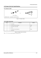
2 Product Specifications 2-5 Interface Specifications 2-5-2-(c) Cable Connection PRINTER SIDE (S.G) 1,7 (SD2) 2 (SD1) 3 (RD2) 4 (RD1) 5 (DR2) 8 (DR1) 9 (CS2) 10 (CS1) 11 XX1 = XX+ XX2 = XX- 485 232 CONVERTER 1,7 (S.G) 2 (RD-) 3 (RD+) 4 (SD-) 5 (SD+) 8 (CS-) 9 (CS+) 10 (DR-) 11 (DR+) HOST SIDE 1,7 (S.G) 3 (RXD) 2 (TXD) 5 (CTS) 6 (DSR) 4 (RTS) 20 (DTR) Figure 2-8 RS-485 Cable Connection 2-5-2-(d) Signal Description Pin No. Signal Name Signal Direction Function BODY Frame GND - Frame Ground 2 SD2 3 SD1 Output Output Transmit Data "H" : SD1 > SD2, "L" : SD1 < SD2 4 RD2 Input Receive Data 5 RD1 Input "H" : RD1 > RD2 (RD1-RD2 0.2V), "L" : RD1 < RD2 (RD1-RD2 0.2V) 7 Signal GND 8 DR2 9 DR1 10 CS2 11 CS1 Output Input Signal Ground When DTR/DSR is selected, this signal indicates whether the printer is BUSY or READY. (H/W flow control) DR1 > DR2 (H) : The printer is BUSY. DR1 < DR2 (L) : The printer is READY. The host computer transmits a data to the host, after confirming this signal. When DTR/DSR is selected, this signal indicates whether the host computer is BUSY or READY. (H/W flow control) CS1 > CS2 (H) : The host computer is BUSY. CS1 < CS2 (L) : The host computer is READY. The printer transmits a data to the host, after confirming this signal. Table 2-14 RS-485 Pin Description 2-12 Samsung Electro-Mechanics
-
 1
1 -
2
-
3
-
4
-
5
-
6
-
7
-
8
-
9
-
10
-
11
-
12
-
13
-
14
-
 15
15 -
 16
16 -
 17
17 -
 18
18 -
 19
19 -
 20
20 -
 21
21 -
 22
22 -
 23
23 -
 24
24 -
 25
25 -
26
-
27
-
28
-
29
-
30
-
31
-
32
-
33
-
34
-
35
-
36
-
37
-
38
-
39
-
40
-
41
-
42
-
43
-
44
-
45
-
46
-
47
-
48
-
49
-
50
-
51
-
52
-
53
-
54
-
55
-
56
-
57
-
58
-
59
-
60
-
61
-
62
-
63
-
64
-
65
-
66
-
67
-
68
-
69
-
70
-
71
-
72
-
73
-
74
-
75
-
76
-
77
-
78
-
79
-
80
-
81
-
82
-
83
-
84
-
85
-
86
-
87
-
88
-
89
-
90
-
91
-
92
-
93
-
94
-
95
-
96
-
97
-
98
-
99
-
100
-
101
-
102
-
103
-
104
-
105
-
106
-
107
-
108
-
109
-
110
-
111
-
112
-
113
-
114
-
115
-
116
-
117
-
118
-
119
-
120
-
121
-
122
-
123
-
124
-
125
 |
 |
