Sanyo PLV Z3 Owners Manual - Page 59
Optional Parts, Configurations of Terminal
 |
View all Sanyo PLV Z3 manuals
Add to My Manuals
Save this manual to your list of manuals |
Page 59 highlights
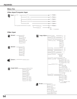
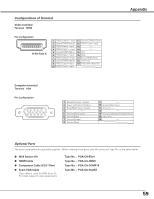
Configurations of Terminal Video terminal Terminal : HDMI Pin Configuration 1 3 5 7 9 11 13 15 17 19 2 4 6 8 10 12 14 16 18 19 Pin Type A 1 TMDS Data 2+ Input 11 Ground (TMDS Clock) 2 Ground (TMDS Data 2) 12 TMDS Clock- Input 3 TMDS Data 2- Input 13 ----- 4 TMDS Data 1+ Input 14 ----- 5 Ground (TMDS Data 1) 15 SCL 6 TMDS Data 1- Input 16 SDA 7 TMDS Data 0+ Input 17 Ground(DDC/CEC) 8 Ground (TMDS Data 0) 18 +5V Pwer 9 TMDS Data 0- Input 19 Plug insetr detection 10 TMDS Clock+ Input Appendix Computer terminal Terminal : VGA Pin Configuration 54 32 1 10 9 8 7 6 15 14 13 12 11 1 Red (R/Cr) Input / Output 2 Green (G/Y) Input / Output 3 Blue (B/Cb) Input / Output 4 ----- 5 Ground (Horiz.sync.) 6 Ground (Red) 7 Ground (Green) 8 Ground (Blue) 9 ----- 10 Ground (Vert.sync.) 11 Ground / ----- 12 ----- 13 Horiz. sync. Input/Output (Composite H/V sync.) 14 Vert. sync. 15 ----- Optional Parts The parts listed below are optionally supplied. When ordering those parts, give the name and Type No. to the sales dealer. ● Wall Anchor Kit ● HDMI Cable ● Component Cable (32.8'/10m) ● Scart-VGA Cable (This cable is used for RGB Scart 21Pin Video output of video equipment.) Type No. : POA-CH-EX01 Type No. : POA-CA-HDMI Type No. : POA-CA-COMP10 Type No. : POA-CA-SCART 59
-
 1
1 -
2
-
3
-
4
-
5
-
6
-
7
-
8
-
9
-
10
-
11
-
12
-
13
-
14
-
15
-
16
-
17
-
18
-
19
-
20
-
21
-
22
-
23
-
24
-
25
-
26
-
27
-
28
-
29
-
30
-
31
-
32
-
33
-
34
-
35
-
36
-
37
-
38
-
39
-
40
-
41
-
42
-
43
-
44
-
45
-
46
-
47
-
48
-
49
-
50
-
51
-
52
-
53
-
 54
54 -
 55
55 -
 56
56 -
 57
57 -
 58
58 -
 59
59 -
 60
60
 |
 |
