Sanyo XU86 Instruction Manual, PLC-XU86 - Page 18
Connecting to a Computer, Cables used for connection
 |
View all Sanyo XU86 manuals
Add to My Manuals
Save this manual to your list of manuals |
Page 18 highlights
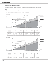
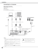
Installation Connecting to a Computer Cables used for connection • VGA Cable (Mini D-sub 15 pin) ✽ •DVI-VGA Cable •USB Cable • Audio Cables ✽ (✽ = Not supplied with this projector.) Audio Output USB port Monitor Output Monitor Output or Monitor Input External Audio Equipment USB cable DVI-VGA cable VGA cable ✽ Audio Input Audio cable (stereo) ✽ USB COMPUTER IN 1/ COMPUTER IN 2 DVI-I /COMPONENT IN /MONITOR OUT This terminal is switchable. Set up the terminal as either Computer input or Monitor output. (See Page 50.) Audio cable ✽ (stereo) RESET USB SERVICE PORT COMPUTER IN 1 DVI-I COMPUTER/ COMPONENT AUDIO IN (VARIABLE) COMPUTER IN 2 / COMPONENT IN MONITOR OUT R AUDIO OUT VIDEO IN L (MONO) COMPUTER / COMPONENT S-VIDEO IN AUDIO IN AUDIO OUT (stereo) 18 ✔Note: •Input sound to the COMPUTER / COMPONENT AUDIO IN terminal when using the COMPUTER IN 1 / DVI-I and the COMPUTER IN 2 / COMPONENT IN / MONITOR OUT terminal as input. • When connecting the AUDIO OUT to external audio equipment, the projector's built-in speaker is disconnected. • When the cable is of the longer variety, it OisN aOdNvisable to use the COMPUTER IN 1 / DVI-I and not the COMPUTER IN 2 / COMPONENT IN / MONITOR OUT. • USB cable connection is needed when operating the computer with the remote control or using the PAGE ed buttons on the remote control. When connecting the cable, the power cords of both the projector and the external equipment should be disconnected from AC outlet.
-
 1
1 -
2
-
3
-
4
-
5
-
6
-
7
-
8
-
9
-
10
-
11
-
12
-
 13
13 -
 14
14 -
 15
15 -
 16
16 -
 17
17 -
 18
18 -
 19
19 -
 20
20 -
 21
21 -
 22
22 -
 23
23 -
24
-
25
-
26
-
27
-
28
-
29
-
30
-
31
-
32
-
33
-
34
-
35
-
36
-
37
-
38
-
39
-
40
-
41
-
42
-
43
-
44
-
45
-
46
-
47
-
48
-
49
-
50
-
51
-
52
-
53
-
54
-
55
-
56
-
57
-
58
-
59
-
60
-
61
-
62
-
63
-
64
-
65
-
66
-
67
-
68
-
69
-
70
-
71
-
72
 |
 |
