Seagate ST19171WC Product Manual - Page 40
Barracuda 9 Product Manual, Rev. C, Mechanical specifications, Typical, Maximum
 |
View all Seagate ST19171WC manuals
Add to My Manuals
Save this manual to your list of manuals |
Page 40 highlights
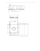
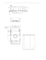
30 Barracuda 9 Product Manual, Rev. C 6.5 Mechanical specifications The following nominal dimensions are exclusive of the decorative front panel accessory. However, dimensions of the front panel are shown in the figure below. Refer to Figures 6, 7, and 8 for detailed mounting configuration dimensions. See Section 8.4, "Drive mounting." Height: Width: Depth: Weight: Typical 1.62 in 4.00 in 5.75 in 2.3 pounds 41.1 mm 101.6 mm 146.05 mm 1.04 kilograms Maximum 1.654 in 4.01 in 5.787 in - 42.0 mm 101.9 mm 147 mm - N P A [1] R F D G E .050 in. (1.27mm) minimum clearance B [5] T [2] U [7] J2 [7] V K J [4] J6 LED W [6] [9] X H S [3] C M L Notes: [1] Mounting holes three on each side, 6-32 UNC. Max screw length into side of drive 0.15 in. (3.81 mm). Screw tightening torque 6.0 in-lb (.675 NM) max with minimum thread engagement of 0.12 in. (3.05 mm). [2] Mounting holes four on bottom, 6-32 UNC. Max screw length into bottom of drive 0.15 in. (3.81 mm). Screw tightening torque 6.0 in-lb (.675 NM) max with minimum thread engagement of 0.12 in. (3.05 mm). [3] Power and interface connections. [4] Decorative front panel. [5] HDA mounting hole to centerline of Pin 1 of power connector. [6] HDA mounting hole to centerline of Pin 1 of J6. Pin ends on J6 are nominally flush with end of drive. [7] HDA mounting hole to centerline of Pin 1 of J2. [8] Dimensions to Pin 1 of each connector are nominal values. [9] HDA mounting hole to centerline of LED lens. Inches Millimeters A 5.750 ± 0.010 146.05 ± .25 B 4.000 ± 0.010 101.60 ± .25 C 1.640 ± 0.020 41.66 ± .51 D 0.625 ± 0.020 15.87 ± .50 E 4.000 ± 0.010 101.60 ± .25 F 0.250 ± 0.005 6.35 ± .13 G 2.375 ± 0.010 60.32 ± .25 H 3.750 ± 0.010 95.25 ± .25 J 2.375 ± 0.010 60.32 ± .25 K 1.750 ± 0.020 44.45 ± .50 L 0.181 ± 0.015 4.60 ± .38 M 0.340 ± 0.015 8.64 ± .38 N 0.190 ± 0.010 4.83 ± .25 P 0.015 max 0.381 max R 1.720 ± 0.010 43.69 ± .25 S 4.100 ± 0.010 104.14 ± .25 T 0.143 3.63 U 0.260 6.60 V 0.030 [8] W 0.405 0.76 [8] 10.28 X 2.265 57.53 Figure 6. Mounting configuration dimensions for "N" models
-
 1
1 -
2
-
3
-
4
-
5
-
6
-
7
-
8
-
9
-
10
-
11
-
12
-
13
-
14
-
15
-
16
-
17
-
18
-
19
-
20
-
21
-
22
-
23
-
24
-
25
-
26
-
27
-
28
-
29
-
30
-
31
-
32
-
33
-
34
-
 35
35 -
 36
36 -
 37
37 -
 38
38 -
 39
39 -
 40
40 -
 41
41 -
 42
42 -
 43
43 -
 44
44 -
 45
45 -
46
-
47
-
48
-
49
-
50
-
51
-
52
-
53
-
54
-
55
-
56
-
57
-
58
-
59
-
60
-
61
-
62
-
63
-
64
-
65
-
66
-
67
-
68
-
69
-
70
-
71
-
72
-
73
-
74
-
75
-
76
-
77
-
78
-
79
-
80
-
81
-
82
-
83
-
84
-
85
-
86
-
87
-
88
-
89
-
90
-
91
-
92
-
93
-
94
 |
 |
