Seagate ST19171WC Product Manual - Page 42
Mounting configuration dimensions for WC and DC models - spec
 |
View all Seagate ST19171WC manuals
Add to My Manuals
Save this manual to your list of manuals |
Page 42 highlights
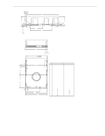
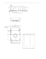
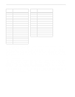
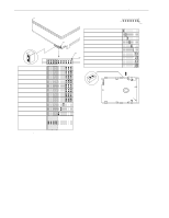
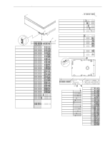
32 Barracuda 9 Product Manual, Rev. C N P A [1] R F D G E .050 in. (1.27mm) minimum clearance [7] [8] T AA U [6] [7] [2] V [10] J2 [10] W K B [5] AA J [4] J6 LED X [9] [12] Y H S [3] C M L Notes: [1] Mounting holes three on each side, 6-32 UNC. Max screw length into side of drive 0.15 in. (3.81 mm). Screw tightening torque 6.0 in-lb (.675 NM) max with minimum thread engagement of 0.12 in. (3.05 mm). [2] Mounting holes four on bottom, 6-32 UNC. Max screw length into bottom of drive 0.15 in. (3.81 mm). Screw tightening torque 6.0 in-lb (.675 NM) max with minimum thread engagement of 0.12 in. (3.05 mm). [3] Interface connector is flush with the end of drive within ±0.020 in. (.5 mm). The interface connector location may extend beyond HDA dimension "A" by 0.020 in. (.5 mm). [4] Decorative front panel (optional). [5] Connector J1 is centered (side to side) on drive within ±0.020 in. (.508 mm). [6] Dimension "U" is from bottom rear drive mounting holes center(s) to the face of the connector at the center of the drive. [7] Dimensions "T" and "U" are unique requirements for SCA drives only, required for conformance with latest ANSI SFF Spec #8337. [8] Maximum connector non-perpendicularity to side planes pointed to by AA. [9] HDA mounting hole to centerline of Pin 1 of J6. Pin ends on J6 are nominally flush with end of drive. [10] HDA mounting hole to centerline of Pin 1 of J2. Dimensions indicated are for reference only. [11] Dimensions to Pin 1 of each connector are nominal values. [12] HDA mounting hole to centerline of LED lens. Inches Millimeters A 5.750 ± 0.010 146.05 ± .25 B 4.000 ± 0.010 101.60 ± .25 C 1.640 ± 0.020 41.66 ± .51 D 0.625 ± 0.020 15.87 ± .50 E 4.000 ± 0.010 101.60 ± .25 F 0.250 ± 0.005 6.35 ± .13 G 2.375 ± 0.010 60.32 ± .25 H 3.750 ± 0.010 95.25 ± .25 J 2.375 ± 0.010 60.32 ± .25 K 1.750 ± 0.020 44.45 ± .50 L 0.181 ± 0.015 4.60 ± .38 M 0.340 ± 0.015 8.64 ± .38 N 0.190 ± 0.010 4.83 ± .25 P 0.015 max 0.381 max R 1.720 ± 0.010 43.69 ± .25 S 4.100 ± 0.010 104.14 ± .25 T 0.150 0.38 U 1.620 ± 0.020 41.15 ± .50 V 0.260 6.60 W 0.030 0.76 X 0.405 [11] 10.28 [11] Y 2.265 57.53 Figure 8. Mounting configuration dimensions for "WC" and "DC" models
-
 1
1 -
2
-
3
-
4
-
5
-
6
-
7
-
8
-
9
-
10
-
11
-
12
-
13
-
14
-
15
-
16
-
17
-
18
-
19
-
20
-
21
-
22
-
23
-
24
-
25
-
26
-
27
-
28
-
29
-
30
-
31
-
32
-
33
-
34
-
35
-
36
-
 37
37 -
 38
38 -
 39
39 -
 40
40 -
 41
41 -
 42
42 -
 43
43 -
 44
44 -
 45
45 -
 46
46 -
 47
47 -
48
-
49
-
50
-
51
-
52
-
53
-
54
-
55
-
56
-
57
-
58
-
59
-
60
-
61
-
62
-
63
-
64
-
65
-
66
-
67
-
68
-
69
-
70
-
71
-
72
-
73
-
74
-
75
-
76
-
77
-
78
-
79
-
80
-
81
-
82
-
83
-
84
-
85
-
86
-
87
-
88
-
89
-
90
-
91
-
92
-
93
-
94
 |
 |
