Seagate ST19171WC Product Manual - Page 62
SCSI Interface Product, Manual., SCSI Interface Product Manual
 |
View all Seagate ST19171WC manuals
Add to My Manuals
Save this manual to your list of manuals |
Page 62 highlights
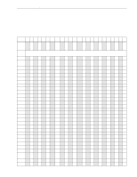
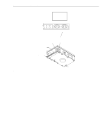
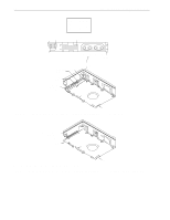
52 Barracuda 9 Product Manual, Rev. C 9.5 Synchronous data transfer The data transfer period to be used by the drive and the initiator is established by an exchange of messages during the Message Phase of operation. See the section on message protocol in the SCSI Interface Product Manual. 9.5.1 Synchronous data transfer periods supported Table 11 lists synchronous data transfer periods supported by the drive. Table 11: Synchronous data transfer periods supported M (Decimal) Transfer period (M times 4 nanoseconds) Transfer rate (mega transfers/second) 12 [1] 15 [1] 18 [1] 25 31 37 50 62 75 87 100 50 [1] 62.5 [1] 75 [1] 100 125 150 200 250 300 350 400 20.0 [1] 16.0 [1] 13.33 [1] 10.0 8.0 6.66 5.0 4.0 3.33 2.86 2.5 [1] Fast-20 (Ultra SCSI) transfer rates. 9.5.2 REQ/ACK offset The maximum REQ/ACK value supported by Barracuda 9 SCSI drives is 15 (0Fh). 9.6 Physical interface Figures 13, 14 and 15 show the locations of the drive physical interface components. The locations of the DC power connector, the SCSI interface connector, and the drive select and option select headers are shown. Details of the physical, electrical and logical characteristics are given in sections following, while the SCSI operational aspects of Seagate drive interfaces are provided in the SCSI Interface Product Manual, part number 77738479. This section describes the connectors, cables, signals, terminators and bus timing of the DC and SCSI I/O interface. See Sections 9.8 and 9.9 for additional terminator information. 9.6.1 DC cable and connector With the exception of "WC" and "DC" model drives, the drive receives DC power through a 4-pin connector (see Figure 13 for pin assignments) mounted at the rear of the main PCB. Recommended part numbers of the mating DC power connector are listed below, but equivalent parts may be used. Type of Cable 14 AWG Connector AMP 1-480424-0 Contacts (20-14 AWG) AMP 60619-4 (loose piece) AMP 61117-4 (strip) Models "WC" and "DC" receive power through the 80-pin I/O connector. See Tables 16 and 17.
-
 1
1 -
2
-
3
-
4
-
5
-
6
-
7
-
8
-
9
-
10
-
11
-
12
-
13
-
14
-
15
-
16
-
17
-
18
-
19
-
20
-
21
-
22
-
23
-
24
-
25
-
26
-
27
-
28
-
29
-
30
-
31
-
32
-
33
-
34
-
35
-
36
-
37
-
38
-
39
-
40
-
41
-
42
-
43
-
44
-
45
-
46
-
47
-
48
-
49
-
50
-
51
-
52
-
53
-
54
-
55
-
56
-
 57
57 -
 58
58 -
 59
59 -
 60
60 -
 61
61 -
 62
62 -
 63
63 -
 64
64 -
 65
65 -
 66
66 -
 67
67 -
68
-
69
-
70
-
71
-
72
-
73
-
74
-
75
-
76
-
77
-
78
-
79
-
80
-
81
-
82
-
83
-
84
-
85
-
86
-
87
-
88
-
89
-
90
-
91
-
92
-
93
-
94
 |
 |
