Seagate ST19171WC Product Manual - Page 65
Barracuda 9 Product Manual, Rev. C, SCSI interface physical description, SCSI interface cable
 |
View all Seagate ST19171WC manuals
Add to My Manuals
Save this manual to your list of manuals |
Page 65 highlights
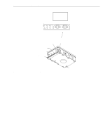
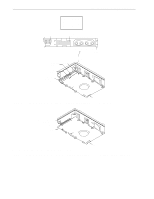
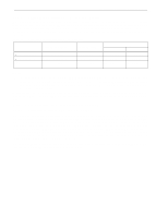
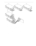
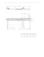
Barracuda 9 Product Manual, Rev. C 55 9.6.2 SCSI interface physical description The drives may be daisy-chained together or with other compatible SCSI devices. Both ends of the cable must be terminated. The "N," "W," and "WC" model drives implement single-ended drivers and receivers. All signals are common between all SCSI devices. The drive may be daisy-chained only with SCSI devices having the same type drivers and receivers. Devices having single-ended interface circuits cannot be on the same daisy chain with devices having differential interface circuits. A maximum of 8 ("N" models) or 16 ("W" and "WC") SCSI devices (including the host) may be daisy-chained together. However, please note the restrictions described in Section 9.6.3 about the number of devices allowed in a daisy chain. The SCSI devices at both ends of the daisy chain are to be terminated. Intermediate SCSI devices shall not be terminated (see Figure 16). Remove the terminator enable jumper TE on J2 select header ("N" and "W" models), or the external terminators ("WD" model), not the terminator power source selector jumper TP (Figures 9 and 10). "WC" and "DC" model drives plug into PCB or bulkhead connectors in the host. They may be connected in a daisy chain by the host backplane wiring or PCB circuit runs that have adequate DC current carrying capacity to support the number of drives plugged into the PCB or bulkhead connectors. A single 80-pin I/O connector cannot support the DC current needs of several drives, so no daisy-chain cables beyond the bulkhead connectors should be used. A single drive connected with a cable to a host 80-pin I/O connector is not recommended. 9.6.3 SCSI interface cable requirements A characteristic impedance as listed in Table 12 is recommended for unshielded flat or twisted pair ribbon cable. To minimize discontinuances and signal reflections, cables of different impedances should not be used in the same bus. Implementations may require trade-offs in shielding effectiveness, cable length, the number of loads, transfer rates, and cost to achieve satisfactory system operation. If you mix shielded and unshielded cables within the same SCSI bus, the effect of impedance mismatch must be carefully considered. Proper impedance matching is especially important to maintain adequate margin at Fast-20 (Ultra SCSI) and transfer rates. "N" models use non-shielded cable connectors. Use a 50-conductor flat cable or 25 twisted pair cable. Use a minimum conductor size of 28 AWG to minimize noise effects. Suggested non-shielded flat cable part numbers are: Flat cable - 35M-3365-50 Twisted pair - Spectra Twist in flat 455-248-50 "W" and "WD" models use non-shielded cable connectors. Use a 68-conductor flat cable or 34 twisted pair cable with connectors listed in 9.6.4.2. Use a minimum conductor size of 28 AWG to minimize noise effects. Suggested non-shielded flat cable part numbers are: Flat cable - 35M-3365-68 Twisted pair - Spectra Twist in flat 455-248-68 "WC" and "DC" models do not require an I/O cable. They are designed to be connected directly to a back panel. Use an 80-pin connector that plugs directly into a PCB or wall/bracket mounted connector in the host equipment. Installations with connectors on cables are not recommended.
-
 1
1 -
2
-
3
-
4
-
5
-
6
-
7
-
8
-
9
-
10
-
11
-
12
-
13
-
14
-
15
-
16
-
17
-
18
-
19
-
20
-
21
-
22
-
23
-
24
-
25
-
26
-
27
-
28
-
29
-
30
-
31
-
32
-
33
-
34
-
35
-
36
-
37
-
38
-
39
-
40
-
41
-
42
-
43
-
44
-
45
-
46
-
47
-
48
-
49
-
50
-
51
-
52
-
53
-
54
-
55
-
56
-
57
-
58
-
59
-
 60
60 -
 61
61 -
 62
62 -
 63
63 -
 64
64 -
 65
65 -
 66
66 -
 67
67 -
 68
68 -
 69
69 -
 70
70 -
71
-
72
-
73
-
74
-
75
-
76
-
77
-
78
-
79
-
80
-
81
-
82
-
83
-
84
-
85
-
86
-
87
-
88
-
89
-
90
-
91
-
92
-
93
-
94
 |
 |
