Seagate ST19171WC Product Manual - Page 51
Barracuda 9 Product Manual, Rev. C, Drive orientation, Cooling, Air flow
 |
View all Seagate ST19171WC manuals
Add to My Manuals
Save this manual to your list of manuals |
Page 51 highlights
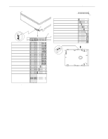
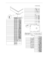
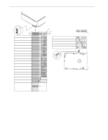
Barracuda 9 Product Manual, Rev. C 41 8.2 Drive orientation The balanced rotary arm actuator design of the drive allows it to be mounted in any orientation. All drive performance characterization, however, has been done with the drive in horizontal (discs level) and vertical (drive on its side) orientations, and these are the two preferred mounting orientations. 8.3 Cooling Cabinet cooling must ensure that the ambient temperature immediately surrounding the drive will not exceed temperature conditions specified in Section 6.4.1. Specific consideration should be given to make sure adequate air circulation is present around the printed circuit board (PCB) to meet the requirements of Section 6.4.1. 8.3.1 Air flow The rack, cabinet, or drawer environment for the drive must provide cooling of the electronics and head and disc assembly (HDA). You should confirm that adequate cooling is provided using the temperature measurement guidelines described below. The drive should be oriented, or air flow directed, so that the least amount of air-flow resistance is created while providing air flow to the electronics and HDA. Also, the shortest possible path between the air inlet and exit should be chosen to minimize the travel length of air heated by the drive and other heat sources within the rack, cabinet, or drawer environment. Possible air-flow patterns are shown in Figure 12. The air-flow patterns are created by one or more fans, either forcing or drawing air as shown in the illustrations. Other air-flow patterns are acceptable as long as the temperature measurement guidelines of Section 6.4.1 are met. Above unit Under unit Note. Air flows in the direction shown (back to front) or in reverse direction (front to back) Note. Air flows in the direction shown or in reverse direction (side to side) Figure 12. Suggested air flow Above unit Under unit
-
 1
1 -
2
-
3
-
4
-
5
-
6
-
7
-
8
-
9
-
10
-
11
-
12
-
13
-
14
-
15
-
16
-
17
-
18
-
19
-
20
-
21
-
22
-
23
-
24
-
25
-
26
-
27
-
28
-
29
-
30
-
31
-
32
-
33
-
34
-
35
-
36
-
37
-
38
-
39
-
40
-
41
-
42
-
43
-
44
-
45
-
 46
46 -
 47
47 -
 48
48 -
 49
49 -
 50
50 -
 51
51 -
 52
52 -
 53
53 -
 54
54 -
 55
55 -
 56
56 -
57
-
58
-
59
-
60
-
61
-
62
-
63
-
64
-
65
-
66
-
67
-
68
-
69
-
70
-
71
-
72
-
73
-
74
-
75
-
76
-
77
-
78
-
79
-
80
-
81
-
82
-
83
-
84
-
85
-
86
-
87
-
88
-
89
-
90
-
91
-
92
-
93
-
94
 |
 |
