Seagate ST19171WC Product Manual - Page 81
SCSI I/O cable ground. See Tables 15 and 17.
 |
View all Seagate ST19171WC manuals
Add to My Manuals
Save this manual to your list of manuals |
Page 81 highlights
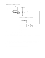
Barracuda 9 Product Manual, Rev. C 71 +5V 5.6K Transmit/Receive Enable [1] DIFFSENS [6] Transmit or Receive Signal [2] +5V TE LSI RE XCVR Disable 1 1 R2 Term Power [5] 330 Ohm [4] 150 Ohm 330 Ohm [3] Twisted or Flat Cable Pair SCSI Device at Beginning of I/O Cable (usually Host Adaptor/Initiator) [7] +5V 5.6K Transmit/Receive Enable [1] DIFFSENS [6] Transmit or Receive Signal [2] +5V TE LSI RE XCVR Disable 1 1 R2 Term Power [5] 330 Ohm [4] 150 Ohm 330 Ohm [7] SCSI Device at End of I/O Cable (Drive/Target) Notes. [1] Positive logic enables transmitter (+5 V = asserted). Negative logic enables receivers (0 V = asserted). [2] Negative logic signal (0 V = asserted). [3] Total interface cable length should not exceed value given in Section 9.6.3.2 from first SCSI device at beginning to end of daisy chain. See Section 9.7.2 for signal characteristics. [4] I/O line terminators. If SCSI device is a Seagate disc drive, terminators and a place to plug them in must be provided external to the drive by user, systems integrator, or host equipment manufacturer where needed. The drive has no terminators and there are no provisions on the drive for terminator installation. [5] Arrangements for connecting terminator power to the terminators must be made by the systems designer. As a help, drive +5 V power is made available on SCSI bus ("N," "W," "ND," and "WD" models) for powering external terminators if the drive option select header jumper TP (Figures 9 and 10) is installed in rightmost position "TP." See pin assignment Tables 15 and 17 for pins assigned to terminator power. [6] SCSI I/O line (pin 21) disables I/O circuits if single-ended cable plugged in or cable plugged in upside down. [7] SCSI I/O cable ground. See Tables 15 and 17. Figure 21. Typical differential I/O line transmitter/receiver and terminators
-
 1
1 -
2
-
3
-
4
-
5
-
6
-
7
-
8
-
9
-
10
-
11
-
12
-
13
-
14
-
15
-
16
-
17
-
18
-
19
-
20
-
21
-
22
-
23
-
24
-
25
-
26
-
27
-
28
-
29
-
30
-
31
-
32
-
33
-
34
-
35
-
36
-
37
-
38
-
39
-
40
-
41
-
42
-
43
-
44
-
45
-
46
-
47
-
48
-
49
-
50
-
51
-
52
-
53
-
54
-
55
-
56
-
57
-
58
-
59
-
60
-
61
-
62
-
63
-
64
-
65
-
66
-
67
-
68
-
69
-
70
-
71
-
72
-
73
-
74
-
75
-
 76
76 -
 77
77 -
 78
78 -
 79
79 -
 80
80 -
 81
81 -
 82
82 -
 83
83 -
 84
84 -
 85
85 -
 86
86 -
87
-
88
-
89
-
90
-
91
-
92
-
93
-
94
 |
 |
