Seagate ST19171WC Product Manual - Page 80
Barracuda 9 Product Manual, Rev. C, Differential drivers/receivers, Differential signals, Output
 |
View all Seagate ST19171WC manuals
Add to My Manuals
Save this manual to your list of manuals |
Page 80 highlights
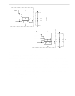
70 Barracuda 9 Product Manual, Rev. C 9.7.2 Differential drivers/receivers Typical differential driver and receiver circuits used by ST19171WD drives are shown in Figure 21. The drive has no provisions for terminator circuits on differential I/O drives. Differential signals All differential interface signals consist of two lines denoted +SIGNAL and -SIGNAL. A signal is true when +SIGNAL is more positive than -SIGNAL, and a signal is false when -SIGNAL is more positive than +SIGNAL. All assigned signals must be terminated at each end of the cable. You must provide external termination for the differential drives. Output characteristics Each signal driven by differential interface drives should have the following output characteristics when measured at the disc drive's SCSI connector: Low-level output voltage* = 2.0 V maximum at low-level output current = 55 milliamps High-level output voltage* = 3.0 V minimum at high-level output current = -55 milliamps Differential voltage = 1.0 V minimum with common-mode voltage ranges from -7 V DC to +12 V DC *Measure these voltages between the output terminal and the SCSI device's logic ground reference. The output characteristics must additionally conform to EIA RS-485-1983. Input characteristics Each signal received by differential interface drives should have the following input characteristics when measured at the disc drive's SCSI connector: Input current on either input = +2.0 milliamps maximum (includes both receivers and passive drivers) This requirement is met with the input voltage varying between -7 V DC and +12 V DC, with power on or off, and with the hysteresis equaling 35 mV minimum. The input characteristics must additionally conform to EIA RS-485-1983.
-
 1
1 -
2
-
3
-
4
-
5
-
6
-
7
-
8
-
9
-
10
-
11
-
12
-
13
-
14
-
15
-
16
-
17
-
18
-
19
-
20
-
21
-
22
-
23
-
24
-
25
-
26
-
27
-
28
-
29
-
30
-
31
-
32
-
33
-
34
-
35
-
36
-
37
-
38
-
39
-
40
-
41
-
42
-
43
-
44
-
45
-
46
-
47
-
48
-
49
-
50
-
51
-
52
-
53
-
54
-
55
-
56
-
57
-
58
-
59
-
60
-
61
-
62
-
63
-
64
-
65
-
66
-
67
-
68
-
69
-
70
-
71
-
72
-
73
-
74
-
 75
75 -
 76
76 -
 77
77 -
 78
78 -
 79
79 -
 80
80 -
 81
81 -
 82
82 -
 83
83 -
 84
84 -
 85
85 -
86
-
87
-
88
-
89
-
90
-
91
-
92
-
93
-
94
 |
 |
