Seagate ST19171WC Product Manual - Page 84
SCSI Interface Product Manual, Interface Product Manual
 |
View all Seagate ST19171WC manuals
Add to My Manuals
Save this manual to your list of manuals |
Page 84 highlights
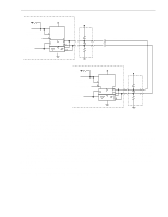
74 Barracuda 9 Product Manual, Rev. C Description Data in byte transfer (parameter) Data out byte transfer (parameter) Next data in byte access (parameter) Next data byte out access (parameter) Data in byte transfer (media) [2] Data out byte transfer (media) [2] Next data in byte access (media [2] Next data in byte access (media [2] MSG IN byte transfer MSG OUT byte transfer STATUS byte transfer Synchronous data transfer characteristics: Request signal transfer period [3] Waveform symbol [1] T24 T25 T26 T27 T28 T29 T30 T31 T32 T33 T34 - Waveform table [1] 4.5-12 4.5-13 4.5-12 4.5-13 4.5-12 4.5-13 4.5-12 4.5-13 4.5-5,7 4.5-8,14,15 4.5-2 4.5-5,8,15 Typical timing 0.04 µs max. 0.04 µs max. 0.10 µs 0.10 µs 0.03 µ 0.03 µ 0.10 µs 0.10 µs 0.09 µs 0.04 µs max. 0.04 µs max. - various Notes. [1] See the SCSI Interface Product Manual, part number 77738479, Section 4.5. [2] Maximum SCSI asynchronous interface transfer rate is given in Section 4.2.3. [3] Synchronous Transfer Period is determined by negotiations between an Initiator and a Drive. The Drive is capable of setting periods as given in Section 9.5. See also Sections 3.1.5.2 and 3.5.3.2 of the SCSI Interface Product Manual, part number 77738479, for a description of synchronous data transfer operation. General timing diagrams for SCSI interface operation are shown in the SCSI Interface Product Manual, part number 77738479, Section 4.5. The specific timing values that apply to this drive are listed in Table 12.
-
 1
1 -
2
-
3
-
4
-
5
-
6
-
7
-
8
-
9
-
10
-
11
-
12
-
13
-
14
-
15
-
16
-
17
-
18
-
19
-
20
-
21
-
22
-
23
-
24
-
25
-
26
-
27
-
28
-
29
-
30
-
31
-
32
-
33
-
34
-
35
-
36
-
37
-
38
-
39
-
40
-
41
-
42
-
43
-
44
-
45
-
46
-
47
-
48
-
49
-
50
-
51
-
52
-
53
-
54
-
55
-
56
-
57
-
58
-
59
-
60
-
61
-
62
-
63
-
64
-
65
-
66
-
67
-
68
-
69
-
70
-
71
-
72
-
73
-
74
-
75
-
76
-
77
-
78
-
 79
79 -
 80
80 -
 81
81 -
 82
82 -
 83
83 -
 84
84 -
 85
85 -
 86
86 -
 87
87 -
 88
88 -
 89
89 -
90
-
91
-
92
-
93
-
94
 |
 |
