Sharp DT 500 DT-500 Operation Manual
Sharp DT 500 - WXGA DLP Projector Manual
 |
UPC - 074000364837
View all Sharp DT 500 manuals
Add to My Manuals
Save this manual to your list of manuals |
Sharp DT 500 manual content summary:
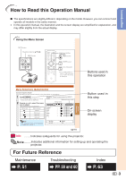
- Sharp DT 500 | DT-500 Operation Manual - Page 1
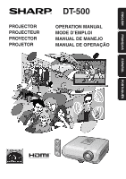
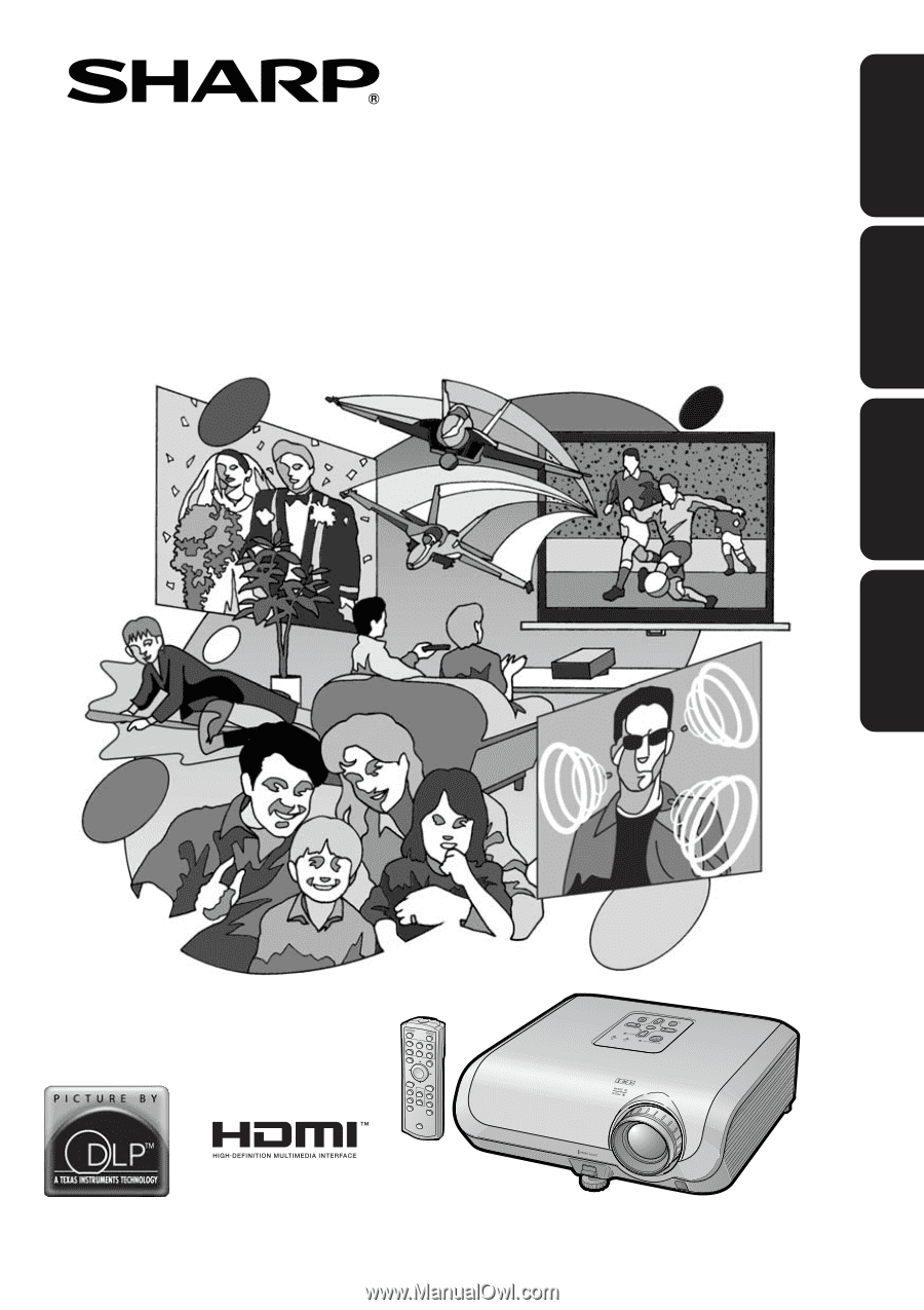
PROJECTOR PROJECTEUR PROYECTOR PROJETOR DT-500 OPERATION MANUAL MODE D'EMPLOI MANUAL DE MANEJO MANUAL DE OPERAÇÃO ESPAÑOL PORTUGUÊS FRANÇAIS ENGLISH - Sharp DT 500 | DT-500 Operation Manual - Page 2
on the bottom of the projector and retain this information. • Before recycling the packaging, please ensure that you have checked the contents of the carton thoroughly against the list of "Supplied accessories" on page 10. Model No.: DT-500 Serial No.: WARNING: High brightness light source. Do not - Sharp DT 500 | DT-500 Operation Manual - Page 3
remote control. Ensure the cooling fan has stopped before disconnecting the power cord. DURING NORMAL OPERATION, NEVER TURN THE PROJECTOR OFF BY DISCONNECTING THE POWER CORD. FAILURE TO OBSERVE THIS WILL RESULT IN PREMATURE LAMP conformity SHARP PROJECTOR, MODEL DT-500 This device complies with Part - Sharp DT 500 | DT-500 Operation Manual - Page 4
Bright Color Tint Sharp Red Blue INPUT 1 Standard 0 0 0 0 0 0 0 Note • The "Fine Sync" menu is not available for INPUT 3 or INPUT 4. SEL./ADJ. RETURN ENTER END 41 Useful Features Button used in this step On-screen display Info ........Indicates safeguards for using the projector. Note - Sharp DT 500 | DT-500 Operation Manual - Page 5
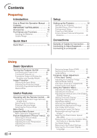
Manual .... 3 Contents 4 IMPORTANT SAFEGUARDS 6 Accessories 10 Part Names and Functions 11 Inserting the Batteries 14 Usable Range 15 Quick Start Quick Start 16 Setup Setting up the Projector 18 Setting up the Projector 18 Standard Setup (Front Projection) ....... 18 Ceiling-mount - Sharp DT 500 | DT-500 Operation Manual - Page 6
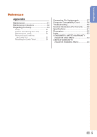
Maintenance Indicators 52 Regarding the Lamp 54 Lamp 54 Caution Concerning the Lamp 54 Replacing the Lamp 54 Removing and Installing the Lamp Unit 55 Resetting the Lamp Timer 56 Connecting Pin Assignments 57 Computer Compatibility Chart 58 Troubleshooting 59 Service Information (For the - Sharp DT 500 | DT-500 Operation Manual - Page 7
marking label. If you are not sure of the type of power supply to your home, consult your product dealer or local power company. For products intended to operate from battery power, or other sources, refer to the operating instructions. 12. Grounding or Polarization This product is provided with one - Sharp DT 500 | DT-500 Operation Manual - Page 8
Ceiling Mounting This product should be mounted to a wall or ceiling only as recommended by the manufacturer. 22. Heat This product should be situated away from heat sources such as radiators, heat registers, stoves, or other products (including amplifiers) that produce heat. • DLP\ (Digital Light - Sharp DT 500 | DT-500 Operation Manual - Page 9
hazard of glass par- ticles if lamp ruptures. In case of lamp rupture, contact your nearest Sharp Authorized Service Center or Dealer for replacement. See "Replacing the Lamp" on page 54. Caution concerning the setup of the projector I For minimal servicing and to maintain high image quality - Sharp DT 500 | DT-500 Operation Manual - Page 10
and turning off the equipment to be connected. I Please read the operation manuals of the projector and the equipment to be connected for instructions on how to make the connections. Using the projector in other countries I The power supply voltage and the shape of the plug may vary depending on - Sharp DT 500 | DT-500 Operation Manual - Page 11
Remote control RRMCGA444WJSB Two R-03 batteries ("AAA" size, UM/SUM-4, HP-16 or similar) Lens cap (attached) CCAPHA024WJSA • Operation manual Power cord for U.S. and Canada, etc. (6' (1.8 m)) QACCDA007WJPZ Optional accessories I Lamp unit I 3 RCA to 15-pin D-sub cable (10' (3.0 m)) AN-100LP - Sharp DT 500 | DT-500 Operation Manual - Page 12
Introduction Part Names and Functions Numbers in Z refer to the main pages in this operation manual where the topic is explained. Projector Top View Power indicator 28, 52 28, 52 Lamp indicator STANDBY/ON 28 button For turning the power on and putting the projector into standby mode. ENTER - Sharp DT 500 | DT-500 Operation Manual - Page 13
Part Names and Functions (Continued) Numbers in Z refer to the main pages in this operation manual where the topic is explained. Rear View 51 Exhaust vent Intake vent 51 AC socket 28 Connect the supplied Power cord. Rear adjustment 31 foot Terminals 15 Remote with HDMI output terminal. 6 - Sharp DT 500 | DT-500 Operation Manual - Page 14
operation manual where the topic is explained. 28 ON button For turning the power on. STANDBY button 29 For putting the projector into button For selecting the appropriate picture. Backlight button For lighting all buttons on the remote control. 38 IRIS button For switching "HIGH BRIGHTNESS - Sharp DT 500 | DT-500 Operation Manual - Page 15
Part Names and Functions (Continued) Inserting the Batteries 1 Press the P mark on the cover and slide with this projector may run down in a short period, depending on how they are kept. Be sure to replace them as soon as possible with new batteries. • Remove the batteries from the remote control if - Sharp DT 500 | DT-500 Operation Manual - Page 16
effective distance of the signal may differ depending on the screen material. When using the remote control • Ensure that you do not drop, expose to moisture or high temperature. • The remote control may malfunction under a fluorescent lamp. In this case, move the projector away from the fluorescent - Sharp DT 500 | DT-500 Operation Manual - Page 17
equipment and plug the power cord into the AC socket of the projector _PP. 22-28 To INPUT 4 terminal AC socket Connect the audio output of any video devices to an appropriate audio device. 3. Remove the lens cap and turn the projector on _P. 28 On the On the remote projector control 16 - Sharp DT 500 | DT-500 Operation Manual - Page 18
confirm the lower left position, the screen adjustments will be set and setup will end. 8. Turn the Power off _P. 29 Press the STANDBY/ON button on the projector or the STANDBY button on the remote control, and then press the button again while the confirmation message is displayed, to put the - Sharp DT 500 | DT-500 Operation Manual - Page 19
optional Sharp ceiling-mount bracket for this installation. Before mounting the projector, contact your nearest Sharp Authorized Service Center or Dealer to obtain the recommended ceiling-mount bracket (sold separately). • AN-XRCM30 ceiling-mount bracket (for U.S.A.). • AN-60KT ceiling-mount bracket - Sharp DT 500 | DT-500 Operation Manual - Page 20
(PRJ) Mode The projector can use any of the 4 projection modes, shown in the diagram below. Select the mode most appropriate for the projection setting in use. (You can set the PRJ Mode in "Options2" menu. See page 49.) I Table mounted, front projection I Ceiling mounted, front projection Setup - Sharp DT 500 | DT-500 Operation Manual - Page 21
(Continued) Picture (Screen) Size and Projection Distance The projection screen size varies according to the distance from the lens of the projector to the screen. Install the projector so that projected images are projected onto the screen at the optimum size by referring to the table below. Use - Sharp DT 500 | DT-500 Operation Manual - Page 22
χ: Picture (Screen) size (diag.) (in/cm) L: Projection distance (ft/m) L1: Minimum projection distance (ft/m) L2: Maximum projection distance (ft/m) H: Distance from the lens center to the bottom of the image (in/cm) S: Adjustable range of image position (in/cm) See page 47. The formula for picture - Sharp DT 500 | DT-500 Operation Manual - Page 23
connection and cables, refer to the operation manual of the connecting equipment. • You may need other cables or connectors not listed below. Equipment Input Signal Cable Terminal on the projector Audio-visual equipment HDMI video HDMI cable (commercially available) INPUT6 Component video - Sharp DT 500 | DT-500 Operation Manual - Page 24
Connecting to Video Equipment Before connecting, ensure that the power cord of the projector is unplugged from the AC outlet and turn off the devices to be connected. After making all connections, turn on the projector first and then the other devices. When connecting the component video equipment - Sharp DT 500 | DT-500 Operation Manual - Page 25
Connecting to Video Equipment (Continued) When connecting to equipment with S-video output terminal (INPUT3) To S-video output terminal DVD, etc. To INPUT3 terminal S-video cable (commercially available) When connecting to equipment with video output terminal (INPUT4) To video output terminal - Sharp DT 500 | DT-500 Operation Manual - Page 26
Connections When connecting the component video equipment to the computer-RGB/ component input terminal on the projector (INPUT5) To component output (Y, CB/PB, CR/PR) terminal DVD, etc. To INPUT5 terminal 3 RCA to 15-pin D-sub cable (optional accessory: AN-C3CP2) 25 - Sharp DT 500 | DT-500 Operation Manual - Page 27
to Video Equipment (Continued) When connecting to equipment with HDMI output teminal (INPUT6) HDMI is a new specialized interface capable of delivering a video and audio signal to the terminal using just one cable. Since this projector does not support an audio signal by itself, use an amplifier or - Sharp DT 500 | DT-500 Operation Manual - Page 28
may not be projected unless the computer's external output port is switched on. (e.g. Press "Fn" and "F5" keys simultaneously when using a SHARP notebook computer). Refer to the specific instructions in your computer's operation manual to enable your computer's external output port. Connections 27 - Sharp DT 500 | DT-500 Operation Manual - Page 29
Remove the lens cap and press S STANDBY/ON on the projector or bON on the remote control. Info • English is the factory default language. If you want to change the on-screen display to another language, change the language according to the procedure on page 50. Lamp indicator Power indicator Note - Sharp DT 500 | DT-500 Operation Manual - Page 30
Turning the Power off (Putting the Projector into Standby Mode) 1 Press SSTANDBY/ON on the projector or aSTANDBY on the remote control, then press that button again while the confirmation message is displayed, to put the projector into standby mode. 2 Unplug the power cord from the AC outlet after - Sharp DT 500 | DT-500 Operation Manual - Page 31
Image Projection (Continued) Adjusting the Projected Image 1 Adjusting the Focus You can adjust the focus with the focus ring on the projector. Rotate the focus ring to adjust the focus while watching the projected image. 2 Adjusting the Screen Size You can adjust the screen size using the - Sharp DT 500 | DT-500 Operation Manual - Page 32
the front adjustment foot comes out. • When lowering the projector, be careful not to get your fingers caught in the area between the adjustment foot and the projector. • Hold the projector firmly while lifting or carrying. • Do not hold by the lens area. Rear adjustment foot Basic Operation 31 - Sharp DT 500 | DT-500 Operation Manual - Page 33
Image Projection (Continued) Correcting Trapezoidal Distortion When the image is projected either from the top or from the bottom towards the screen at an angle, the image becomes distorted trapezoidally.The function for correcting trapezoidal distortion is called Keystone Correction. There are the - Sharp DT 500 | DT-500 Operation Manual - Page 34
Press c KEYSTONE on the remote control. • "GEOMETRIC ADJUSTMENT" will be displayed. • Each time c KEYSTONE is pressed , the changes are saved even if the power cord is unplugged. • Since Keystone correction correction, change the placement position of the projector. • Straight lines and the edges - Sharp DT 500 | DT-500 Operation Manual - Page 35
by setting "RESIZE" to "STRETCH" (16:9). 1 Press c KEYSTONE on the remote control repeatedly until "GEOMETRIC ADJUSTMENT" is displayed. 2 RESET NEXT END Geometric Adjustment Blue area Screen Upper Left Upper Right 4 Press i ENTER to set the position. • The arrow in the upper right turns red - Sharp DT 500 | DT-500 Operation Manual - Page 36
confirmation screen displays before the "H & V KEYSTONE" screen, asking if you want to reset the adjustments or not. Then select RESET. R On-screen display H&V KEYSTONE END ENTER ADJUST RESET 3 Press P or R on the remote control to align the left and right sides of the projected image. Vertical - Sharp DT 500 | DT-500 Operation Manual - Page 37
you can choose "STRETCH", "SIDE BAR", "CINEMA ZOOM" or "DOT BY DOT (Computer input only)" image. Press m RESIZE on the projector or jRESIZE on the remote control. On the projector On the remote control RESIZE button VIDEO RESIZE button • "STRETCH" is fixed when 540P, 720P or 1080I signals are - Sharp DT 500 | DT-500 Operation Manual - Page 38
(4:3), if you use the RESIZE function to fill the screen or use the Overscan function to change the aspect ratio of a fixed-ratio input signal, parts of the outer edge of the image will be cut off or distorted. To watch original images as the producers intended, set RESIZE to "SIDE - Sharp DT 500 | DT-500 Operation Manual - Page 39
MODE button IRIS button FREEZE button Switching the Iris Setting This function controls the quantity of the projected light and the contrast of the image. Press lIRIS. • Each time the button is pressed while the display is on, the mode is switched in the following order: HIGH BRIGHTNESS MODE HIGH - Sharp DT 500 | DT-500 Operation Manual - Page 40
+30 Bright -30 +30 Color -30 +30 *2 Tint -30 +30 *2 Sharp -30 +30 *2 Red -30 +30 Blue -30 +30 Page 43 PAGE 2 Picture Picture Mode CLR Temp BrilliantColor™ C. M. S. Progressive DNR IRIS Lamp Setting Reset SEL./ADJ. RETURN 7500K 1 INPUT 1 Standard 3D Progressive Level 1 High Brightness - Sharp DT 500 | DT-500 Operation Manual - Page 41
2 PRJ Mode RS-232C STANDBY Mode Fan Mode All Reset Language INPUT 1 Front 9600 bps Eco Normal English SEL./ADJ HDMI Setting Page 48 Background Page 48 Auto Power Off [On/Off] Page 49 Lamp Timer(Life) Page 49 PRJ Mode Page 49 Standard Enhanced Blue None Sub menu Front Ceiling + Front Rear Ceiling - Sharp DT 500 | DT-500 Operation Manual - Page 42
. 2 Press Q or O to select the menu icon to adjust. • The selected icon is highlighted. Menu icon Menu screen Picture Fine Sync Options1 Options2 Example: "Picture" screen menu for INPUT 1 mode Selected input mode Menu icons Picture Picture Mode Contrast Bright Color Tint Sharp Red Blue - Sharp DT 500 | DT-500 Operation Manual - Page 43
is stored. Picture Picture Mode Contrast Bright Color Tint Sharp Red Blue INPUT 1 Standard 0 15 0 0 0 0 0 5 Press dMENU. • The menu screen will disappear. SEL./ADJ. RETURN Single ADJ END Note • The d MENU button does not function while the projector is operating the "Auto Sync" or "FREEZE - Sharp DT 500 | DT-500 Operation Manual - Page 44
Sharp Red Blue INPUT 1 Standard 0 0 0 0 0 0 0 Q PAGE 2 Picture Picture Mode CLR Temp BrilliantColor™ C. M. S. Progressive DNR IRIS Lamp Setting Reset you make are retained in memory. Note • You can also press k PICTURE MODE on the remote control to select the picture mode. (See page 38.) 2 - Sharp DT 500 | DT-500 Operation Manual - Page 45
. • To reset the adjustment values of each color to the default settings, select "Reset" and press i ENTER. Info blue Closer to magenta Closer to red 44 Selectable items Description 2D Useful encoded as is at 24 frames/second. The projector can convert this film source to progressive video - Sharp DT 500 | DT-500 Operation Manual - Page 46
function controls the quantity of the projected light and the contrast of the image. remote control to change the Iris. (See page 38.) 8 Lamp Setting Selectable items Brightness Bright 100% Eco + Approx. Quiet 87% Fan sound Normal Low Power consumption (When using AC 100V) 355W 310W Lamp - Sharp DT 500 | DT-500 Operation Manual - Page 47
in the "Fine Sync" menu to "On" or pressing f AUTO SYNC on the remote control. • "Clock", "Phase", "H-Pos" and "V- reset all adjustment items, select "Reset" and press i ENTER. 3 Auto Sync (Auto Sync Adjustment) Selectable items On Off Description Auto Sync adjustment will occur when the projector - Sharp DT 500 | DT-500 Operation Manual - Page 48
Video System 6 Signal Type 7 HDMI Setting 8 Background 9 Auto Power Off 0 Lamp Timer(Life) INPUT 1 0 0 You can also use the IMAGE SHIFT buttons on the remote control to adjust the image position. 3 Adjusting the of the screen rises, but also the upper part is changed to a certain point. • - Sharp DT 500 | DT-500 Operation Manual - Page 49
Type" using g RGB/COMP. on the remote control (INPUT 5 or INPUT 6). 7 Selecting the HDMI Setting SECAM NTSC4.43 NTSC3.58 When connected output signal type and the projector's input signal type do not match. If this should occur, switch the HDMI Setting. Selectable items Description Standard - Sharp DT 500 | DT-500 Operation Manual - Page 50
no input signal is detected for more than 15 minutes, the projector will automatically enter standby mode. The Auto Power Off function will be disabled. Options 2 1 PRJ Mode 2 RS-232C 3 STANDBY Mode 4 Fan Mode 5 All Reset 6 Language Menu operation n Page 41 INPUT 1 Front 9600 bps Eco Normal - Sharp DT 500 | DT-500 Operation Manual - Page 51
using the projector at altitudes of approximately 4,900 feet (1,500 meters) or This reduces power consumption when the projector is in standby mode. Use "All Reset" to Lamp Timer (Life) - Language Selectable items Description Standard The RS-232C function is activated even if the projector - Sharp DT 500 | DT-500 Operation Manual - Page 52
the surface of the lens. I As the surface of the lens can easily get damaged, be sure not to scrape or hit the lens. Cleaning the exhaust and air vents during projector operation, be sure to press S STANDBY/ON on the projector or aSTANDBY on the remote control and put the projector into standby mode - Sharp DT 500 | DT-500 Operation Manual - Page 53
Indicators I The warning lights (power indicator, lamp indicator and temperature warning indicator) on the projector indicate problems inside the projector. I If a problem occurs, either the temperature warning indicator or the lamp indicator will illuminate red, and the projector will enter standby - Sharp DT 500 | DT-500 Operation Manual - Page 54
it again. • Carefully replace the lamp. (See page 55.) • Take the projector to your nearest Sharp Authorized Service Center or Dealer for repair. • Please exercise care when replacing the lamp. • Securely install the cover. • If the power indicator blinks in red even when the lamp unit cover is - Sharp DT 500 | DT-500 Operation Manual - Page 55
change the lamp by following the instructions described in this section. * If you wish, you may have the lamp replaced at your nearest Sharp Authorized Service Center or Dealer. * If the new lamp does not light after replacement, take your projector to the nearest Sharp Authorized Service Center or - Sharp DT 500 | DT-500 Operation Manual - Page 56
the power cord from the AC socket. • Leave the lamp until it has fully cooled down (about 1 hour). 3 Remove the lamp unit cover. • Turn the projector over. Loosen the user service screw (1) that secures the lamp unit cover. Remove the lamp unit cover (2). 1 2 User service screw (for lamp unit - Sharp DT 500 | DT-500 Operation Manual - Page 57
user service screw to secure the lamp unit cover. Info • If the lamp unit and lamp unit cover are not correctly installed, the power will not turn on, even if the power cord is connected to the projector. Securing screws 2 1 Resetting the Lamp Timer Reset the lamp timer after replacing the lamp - Sharp DT 500 | DT-500 Operation Manual - Page 58
input (blue) 11 15 4. Not connected 5. Not connected 6. Earth (red) 7. Earth (green/sync on green) 8. Earth (blue) 9. Not . Not connected 13. Not connected 14. Not connected 15. Not connected HDMI Terminal 1 19 2 18 Pin No. Name 1. TMDS Data2+ 2. Power 19. Hot Plug Detect Appendix 57 - Sharp DT 500 | DT-500 Operation Manual - Page 59
75 85 50 56 60 70 72 75 85 50 60 70 75 60 60 67 60 75 75 VESA Standard ✔ ✔ HDMI Support ✔ Display Upscale True Upscale True Note • When this projector receives 640K350 VESA format VGA signals, "640K400" appears on the screen. DTV Signal 480I 480P 540P 576I 576P 720P 1035I 1035I - Sharp DT 500 | DT-500 Operation Manual - Page 60
Troubleshooting Problem Check Picure does not appear or projector does not start. No picture appears (or picture is dark). • Projector power cord is not plugged into the wall outlet. • Power to the external connected devices is off. • The selected input mode is wrong. • Cables incorrectly - Sharp DT 500 | DT-500 Operation Manual - Page 61
the HDMI Setting ("Standard" or "Enhanced") that results in the best picture quality. The cooling fan becomes • When temperature inside the projector increases, the cooling fan noisy. runs faster. The lamp does not light • The lamp indicator is illuminating in red. up even after the Replace - Sharp DT 500 | DT-500 Operation Manual - Page 62
Specifications Product type Projector Model DT-500 Video system NTSC3.58/NTSC4. parts) Weight (approx.) 8.8 lbs. (4.0 kg) Replacement parts Remote control, Power cord for U.S. and Canada, etc., Operation manual *1 When STANDBY Mode is set to "Eco" As a part of policy of continuous improvement, SHARP - Sharp DT 500 | DT-500 Operation Manual - Page 63
Dimensions Units: inches (mm) 13 64/ (5) 11 1/32 (280) 23 64/ (9) 2 7/8 (73) 1 55 64/ (47) 7/16 (11) 4 19 64/ (109) ø9 7/64 (69.2) 3 5/32 (80) 12 /13 32 (315) 3 1/16 (77.5) 62 1 /11 32 (33.8) 2 /61 64 (75) 1 /53 64 (46.2) 2 /19 32 (65.5) 7/16 (11) 1 7/8 (47.5) 4 7/64 (104) - Sharp DT 500 | DT-500 Operation Manual - Page 64
30 FREEZE button 38 GEOMETRIC ADJUSTMENT 34 H & V KEYSTONE 35 HDMI Setting 48 H-Pos 46 HEIGHT ADJUST lever 30 Hue 44 Image Shift Power cord 28 PRJ Mode 19, 49 Progressive 44 R-03 batteries 14 Rear adjustment foot 31 Red 43 Remote control 13 Remote control sensor 15 Replacing the lamp - Sharp DT 500 | DT-500 Operation Manual - Page 65
DT-500 Projector 64 - Sharp DT 500 | DT-500 Operation Manual - Page 66
Appendix 65
-
 1
1 -
 2
2 -
 3
3 -
 4
4 -
 5
5 -
 6
6 -
 7
7 -
8
-
9
-
10
-
11
-
12
-
13
-
14
-
15
-
16
-
17
-
18
-
19
-
20
-
21
-
22
-
23
-
24
-
25
-
26
-
27
-
28
-
29
-
30
-
31
-
32
-
33
-
34
-
35
-
36
-
37
-
38
-
39
-
40
-
41
-
42
-
43
-
44
-
45
-
46
-
47
-
48
-
49
-
50
-
51
-
52
-
53
-
54
-
55
-
56
-
57
-
58
-
59
-
60
-
61
-
62
-
63
-
64
-
65
-
66
 |
 |
ENGLISH
FRANÇAIS
DT-500
ESPAÑOL
PORTUGUÊS
OPERATION MANUAL
MODE D’EMPLOI
MANUAL DE MANEJO
MANUAL DE OPERAÇÃO
PROJECTOR
PROJECTEUR
PROYECTOR
PROJETOR