Sharp DT 500 DT-500 Operation Manual - Page 35
Repeat the same procedure
 |
UPC - 074000364837
View all Sharp DT 500 manuals
Add to My Manuals
Save this manual to your list of manuals |
Page 35 highlights
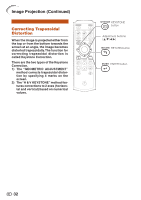
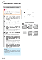
Image Projection (Continued) GEOMETRIC ADJUSTMENT Info • When adjusting a 4:3-aspect-ratio input signal to a 4:3-aspect-ratio screen, correct the trapezoidal distortion by setting "RESIZE" to "STRETCH" (16:9). 1 Press c KEYSTONE on the remote control repeatedly until "GEOMETRIC ADJUSTMENT" is displayed. 2 Adjust the focus, size, and projection angle so that the screen edges line up into the blue area. • Line up the screen edges into the blue area as closely as possible. 3 Press P, R, O or Q to move the position for the upper left of the image. • Adjust the screen until the displayed red arrows line up in the upper left. R On-screen display Adjust upper left corner GEOMETRIC ADJUSTMENT ADJUST RESET NEXT END Geometric Adjustment Blue area Screen Upper Left Upper Right 4 Press i ENTER to set the position. • The arrow in the upper right turns red. 5 Repeat the same procedure with the positions for the upper right, lower right and lower left of the image. • When you press e RETURN at this point, you will return to the previous screen. • If you press e RETURN before adjusting the upper left corner, the Reset Confirmation screen displays. • When you confirm the lower left position, the screen adjustments will be set and the "GEOMETRIC ADJUSTMENT" mode will end. Lower Left Lower Right Note • The placement of the screen and the projector may result in the image aspect ratio becoming slightly distorted. • Try "H&V KEYSTONE" when "GEOMETRIC ADJUSTMENT" does not fully correct trapezoidal distortion. 34
-
 1
1 -
2
-
3
-
4
-
5
-
6
-
7
-
8
-
9
-
10
-
11
-
12
-
13
-
14
-
15
-
16
-
17
-
18
-
19
-
20
-
21
-
22
-
23
-
24
-
25
-
26
-
27
-
28
-
29
-
 30
30 -
 31
31 -
 32
32 -
 33
33 -
 34
34 -
 35
35 -
 36
36 -
 37
37 -
 38
38 -
 39
39 -
 40
40 -
41
-
42
-
43
-
44
-
45
-
46
-
47
-
48
-
49
-
50
-
51
-
52
-
53
-
54
-
55
-
56
-
57
-
58
-
59
-
60
-
61
-
62
-
63
-
64
-
65
-
66
 |
 |
