Sony DAV-LF1H Operating Instructions - Page 22
Step 2: Connecting the System, Refer to the connection diagram below
 |
View all Sony DAV-LF1H manuals
Add to My Manuals
Save this manual to your list of manuals |
Page 22 highlights
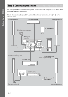
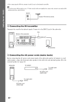
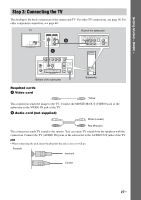
Getting Started - BASIC - Step 2: Connecting the System This hookup is the basic connection of the system. For TV connections, see pages 27 and 36. For other component connection, see page 40. Refer to the connection diagram below, and read the additional information from 1 to 6 on the following pages. 2 Front speaker (L) 2 Center speaker 2 Front speaker (R) 4 AM loop antenna (aerial) 5 IR transmitter Bottom of the subwoofer VIDEO IN VIDEO IN VIDEO 1 VIDEO 2 Y PB/CB PR/CR COMPONENT VIDEO OUT AM VIDEO S-VIDEO MONITOR OUT FM 75 COAXIAL SYSTEM CONTROL DIR-T1 SPEAKER INPEDANCE CENTER USE 4 FRONT L FRONT R Subwoofer 4 FM wire antenna (aerial) 1 Control unit 6 AC power cord (mains lead) SA-TSLF1H DIR-R3 3 AC adaptor Surround speaker (L) 22US 6 AC power cord (mains lead) Surround speaker (R)
-
 1
1 -
2
-
3
-
4
-
5
-
6
-
7
-
8
-
9
-
10
-
11
-
12
-
13
-
14
-
15
-
16
-
 17
17 -
 18
18 -
 19
19 -
 20
20 -
 21
21 -
 22
22 -
 23
23 -
 24
24 -
 25
25 -
 26
26 -
 27
27 -
28
-
29
-
30
-
31
-
32
-
33
-
34
-
35
-
36
-
37
-
38
-
39
-
40
-
41
-
42
-
43
-
44
-
45
-
46
-
47
-
48
-
49
-
50
-
51
-
52
-
53
-
54
-
55
-
56
-
57
-
58
-
59
-
60
-
61
-
62
-
63
-
64
-
65
-
66
-
67
-
68
-
69
-
70
-
71
-
72
-
73
-
74
-
75
-
76
-
77
-
78
-
79
-
80
-
81
-
82
-
83
-
84
-
85
-
86
-
87
-
88
-
89
-
90
-
91
-
92
-
93
-
94
-
95
-
96
-
97
-
98
-
99
-
100
-
101
-
102
-
103
-
104
-
105
-
106
-
107
-
108
-
109
-
110
-
111
-
112
-
113
-
114
-
115
-
116
-
117
-
118
-
119
-
120
-
121
-
122
-
123
-
124
-
125
-
126
-
127
 |
 |
