Sony EVIHD7V Product Manual (HD Color Video Camera) - Page 20
VISCA Communication, Specifications, Timing Chart, VISCA packet structure
 |
View all Sony EVIHD7V manuals
Add to My Manuals
Save this manual to your list of manuals |
Page 20 highlights
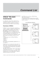
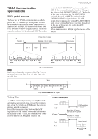
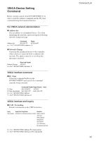
VISCA Communication Specifications VISCA packet structure The basic unit of VISCA communication is called a packet (Fig. 2). The first byte of the packet is called the header and comprises the sender's and receiver's addresses. For example, the header of the packet sent to the EVI-HD7V/HD3V assigned address 1 from the controller (address 0) is hexadecimal 81H. The packet Command List sent to the EVI-HD7V/HD3V assigned address 2 is 82H. In the command list, as the header is 8X, input the address of the EVI-HD7V/HD3V at X. The header of the reply packet from the EVI-HD7V/HD3V assigned address 1 is 90H. The packet from the EVI-HD7V/HD3V assigned address 2 is A0H. Some of the commands for setting EVI-HD7V/HD3V units can be sent to all devices at one time (broadcast). In the case of broadcast, the header should be hexadecimal 88H. When the terminator is FFH, it signifies the end of the packet. Header Packet (3 to 16 bytes) Message (1 to 14 bytes) Terminator Byte 1 Byte 2 Byte 3 FF Sender's 1 address 0 Receiver's address Bit 7 Bit 6 Bit 5 Bit 4 Bit 3 Bit 2 Bit 1 Bit 0 (MSB) (LSB) 11 11 1111 Bit 7 Bit 6 Bit 5 Bit 4 Bit 3 Bit 2 Bit 1 Bit 0 (MSB) (LSB) Fig. 2 Packet structure Note Fig. 2 shows the packet structure, while Fig. 3 shows the actual waveform. Data flow will take place with the LSB first. 1 byte Start bit Bit 0 Bit 1 Bit 2 Bit 3 Bit 4 Bit 5 Bit 6 Bit 7 Stop bit. (LSB) (MSB) Fig. 3 Actual waveform for 1 byte. Timing Chart As VISCA command processing can only be carried out one time per vertical cycle, it takes the minimum time of one V cycle for an ACK/Inquiry Packet to be returned after the command. Even if the transmission time between the ACK/ Inquiry Packet and the next command is shorter than the duration of one V cycle, the command will not be received until the ACK/Inquiry Packet is sent. General Commands Command ACK Completion More than 16.7 msec (20 msec 50 Hz system) Query Commands More than 16.7 msec (20 msec 50 Hz system) Command Inquiry Packet 16 Byte 20
-
 1
1 -
2
-
3
-
4
-
5
-
6
-
7
-
8
-
9
-
10
-
11
-
12
-
13
-
14
-
 15
15 -
 16
16 -
 17
17 -
 18
18 -
 19
19 -
 20
20 -
 21
21 -
 22
22 -
 23
23 -
 24
24 -
 25
25 -
26
-
27
-
28
-
29
-
30
-
31
-
32
-
33
-
34
-
35
-
36
-
37
-
38
-
39
-
40
 |
 |
