Sony EVIHD7V Product Manual (HD Color Video Camera) - Page 5
Locations of Controls
 |
View all Sony EVIHD7V manuals
Add to My Manuals
Save this manual to your list of manuals |
Page 5 highlights
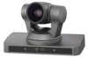
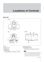
Locations of Controls Locations of Controls Main Unit Front Rear Bottom 1 Lens 2 Remote sensors 3 POWER lamp 4 STANDBY lamp For detailed information on LED status of the POWER lamp and STANDBY lamp, see "LED Status" on page 37. 5 DC IN 12V connector 6 SYSTEM SELECT switch This switch allows you to select the video format of the signal to be output from the VIDEO OUT connectors. Notes • Be sure to set this switch before you turn on the power of the camera. You can also set this switch in the standby mode of the camera. After completing the setting, turn on the power of the camera by connecting it to an AC outlet using the supplied AC power adaptor and AC power cord, or by using (Continued) 5
-
 1
1 -
 2
2 -
 3
3 -
 4
4 -
 5
5 -
 6
6 -
 7
7 -
 8
8 -
 9
9 -
 10
10 -
 11
11 -
12
-
13
-
14
-
15
-
16
-
17
-
18
-
19
-
20
-
21
-
22
-
23
-
24
-
25
-
26
-
27
-
28
-
29
-
30
-
31
-
32
-
33
-
34
-
35
-
36
-
37
-
38
-
39
-
40
 |
 |

5
Locations of Controls
Main Unit
Front
Rear
Bottom
(Continued)
1
Lens
2
Remote sensors
3
POWER lamp
4
STANDBY lamp
For detailed information on LED status of the POWER
lamp and STANDBY lamp, see “LED Status” on page 37.
5
DC IN 12V connector
6
SYSTEM SELECT switch
This switch allows you to select the video format of the
signal to be output from the VIDEO OUT connectors.
Notes
•
Be sure to set this switch before you turn on the power of the
camera. You can also set this switch in the standby mode of
the camera. After completing the setting, turn on the power
of the camera by connecting it to an AC outlet using the
supplied AC power adaptor and AC power cord, or by using