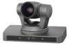
Sony EVIHD7V Product Manual (HD Color Video Camera) - Page 23
Pin assignment, EVI-HD7V/HD3V, Windows D-sub 25 pin, EVI Camera or Mini, DIN 8 pin serial
 |
View all Sony EVIHD7V manuals
Add to My Manuals
Save this manual to your list of manuals |
Page 23 highlights
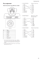
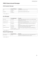
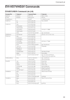
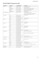
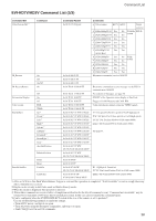
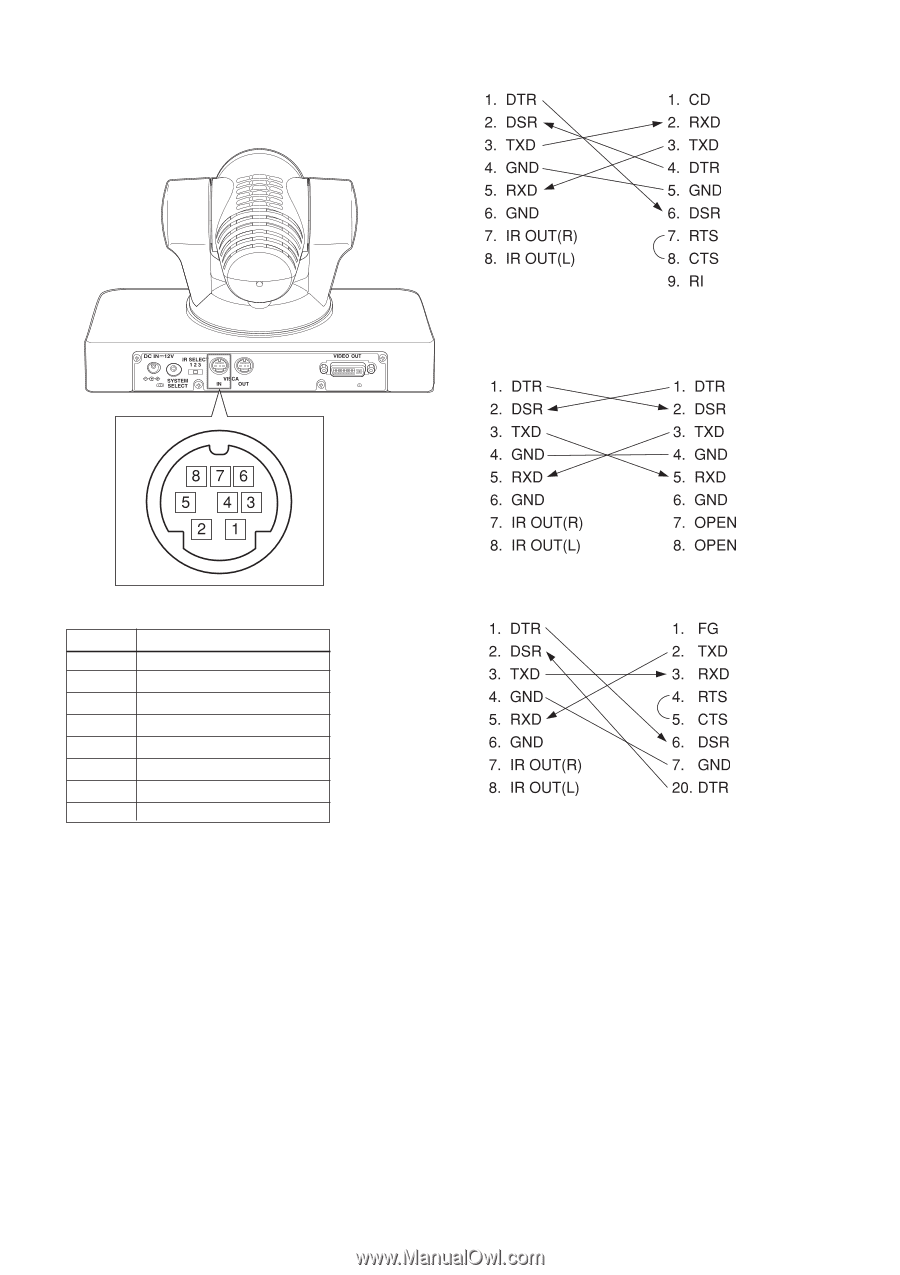
Pin assignment VISCA IN connector (mini-DIN 8-pin, female) • EVI-HD7V/HD3V Command List Windows D-sub 9 pin • EVI-HD7V/HD3V EVI Camera or Mini DIN 8 pin serial VISCA IN No Pins 1 DTR IN* 2 DSR IN* 3 TXD IN 4 GND 5 RXD IN 6 GND 7 IR OUT (R)** 8 IR OUT (L)** * The "IN" in the function names for pins 1 and 2 ("DTR IN" and "DSR IN") are in reference to being within the VISCA IN connector. For details on signal direction, see the diagrams to the right. ** You can change ON/OFF of IR OUT of pins 7 and 8 using the BOTTOM switch (see page 7). • EVI-HD7V/HD3V Windows D-sub 25 pin 23
-
 1
1 -
2
-
3
-
4
-
5
-
6
-
7
-
8
-
9
-
10
-
11
-
12
-
13
-
14
-
15
-
16
-
17
-
 18
18 -
 19
19 -
 20
20 -
 21
21 -
 22
22 -
 23
23 -
 24
24 -
 25
25 -
 26
26 -
 27
27 -
 28
28 -
29
-
30
-
31
-
32
-
33
-
34
-
35
-
36
-
37
-
38
-
39
-
40
 |
 |
23
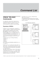
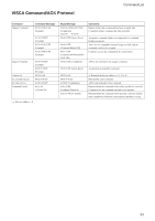
Command List
•
EVI-HD7V/HD3V
Windows D-sub 25 pin
Pin assignment
VISCA IN connector (mini-DIN 8-pin, female)
*
The “IN” in the function names for pins 1 and 2 (“DTR IN”
and “DSR IN”) are in reference to being within the VISCA IN
connector. For details on signal direction, see the diagrams to
the right.
**
You can change ON/OFF of IR OUT of pins 7 and 8 using the
BOTTOM switch (see page 7).
•
EVI-HD7V/HD3V
EVI Camera or Mini
DIN 8 pin serial
•
EVI-HD7V/HD3V
Windows D-sub 9 pin
VISCA
IN
No
Pins
1
DTR IN*
2
DSR IN*
3
TXD IN
4
GND
5
RXD IN
6
GND
7
IR OUT (R)**
8
IR OUT (L)**