Sony EVIHD7V Product Manual (HD Color Video Camera) - Page 6
IR SELECT switch, VISCA IN connector, distortion on a monitor that uses the 4:3 aspect ratio. - manual
 |
View all Sony EVIHD7V manuals
Add to My Manuals
Save this manual to your list of manuals |
Page 6 highlights
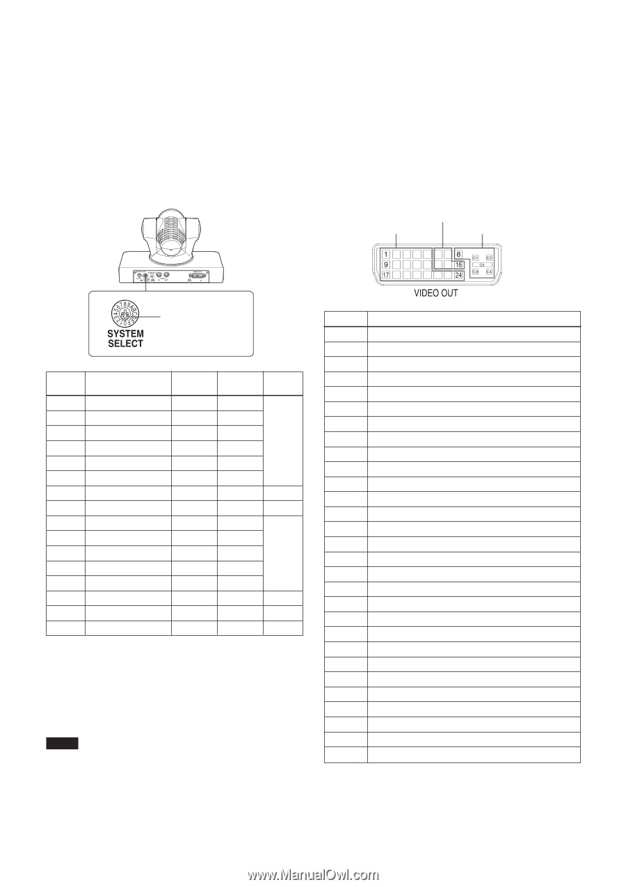
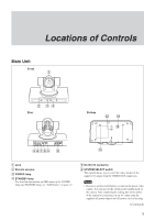
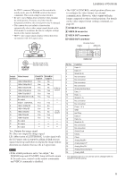
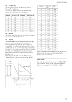
the VISCA command. When you set this switch in the standby mode, press the POWER switch of the remote commander. This switch setting becomes effective. • Be sure to use a Phillips-head screwdriver when changing the switch position. If you use a tool other than the designated screwdriver, the crossed groove may be damaged. • This camera does not include a function that automatically selects video output signals based on the DVI monitor's resolution. Be sure to configure settings based on the monitor manually. • HDTV video signal outputs display without distortion on monitors with 16:9 aspect ratios. Locations of Controls • The VISCA CONTROL switch position allows you to configure the video format via external communication. However, video output will take longer compared to other switch positions. For details on the video output format settings command, see page 28. 7 IR SELECT switch 8 VISCA IN connector 9 VISCA OUT connector 0 VIDEO OUT connector PLUG & PLAY TMDS ANALOG Set this arrow to the desired video format. Switch Video format position EVI-HD7V EVI-HD3V support support 0 1920×1080p/59.94 Yes No 1 1920×1080p/29.97 Yes No 2 1920×1080i/59.94 Yes No 59.94 Hz 3 1280×720p/59.94 Yes Yes system 4 1280×720p/29.97 Yes Yes 5 640×480p/59.94 (LB) Yes Yes 6 No output - - - 7 VISCA CONTROL Yes Yes - 8 1920×1080p/50 Yes No 9 1920×1080p/25 A 1920×1080i/50 B 1280×720p/50 Yes No Yes No 50 Hz system Yes Yes C 1280×720p/25 Yes Yes D No output - - - E No output - - - F No output - - - Yes: Outputs the image signal. No: Does not output the image signal LB: Abbreviation of LETTER BOX. A video signal with the 16:9 aspect ratio is output by adding a blank area (no signal, black) top and bottom to display the image without distortion on a monitor that uses the 4:3 aspect ratio. Notes • If the switch position is set to "no output," the POWER lamp and STANDBY lamp will both remain lit. In such cases, control via the remote commander and VISCA commands is disabled. Pin No. 1 2 3 4 5 6 7 8 9 10 11 12 13 14 15 16 17 18 19 20 21 22 23 24 C1 C2 C3 C4 C5 Function Data_2Data_2+ Shield (2, 4) No connection No connection No connection No connection Analog Vertical Sync Data_1Data_1+ Shield (1, 3) No connection No connection Power_+5 V GND Hot Plug Data_0Data_0+ Shield (0, 5) No connection No connection Shield Clock Clock+ ClockAnalog Red/Pr* Analog Green/Y* Analog Blue/Pb* Analog Horizontal Sync Analog GND * The signals for pins C1, C2, and C3 can be changed with the COLOR SYSTEM setting. 6
-
 1
1 -
 2
2 -
 3
3 -
 4
4 -
 5
5 -
 6
6 -
 7
7 -
 8
8 -
 9
9 -
 10
10 -
 11
11 -
 12
12 -
13
-
14
-
15
-
16
-
17
-
18
-
19
-
20
-
21
-
22
-
23
-
24
-
25
-
26
-
27
-
28
-
29
-
30
-
31
-
32
-
33
-
34
-
35
-
36
-
37
-
38
-
39
-
40
 |
 |