Sony F23 Product Manual (F23 Operation Manual 1st edition)
Sony F23 Manual
 |
View all Sony F23 manuals
Add to My Manuals
Save this manual to your list of manuals |
Sony F23 manual content summary:
- Sony F23 | Product Manual (F23 Operation Manual 1st edition) - Page 1
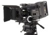
DIGITAL CINEMATOGRAPHY CAMERA F23 OPERATION MANUAL [English] 1st Edition - Sony F23 | Product Manual (F23 Operation Manual 1st edition) - Page 2
if not installed and used in accordance with the instruction manual, may cause harmful interference to radio communications. Operation curité des produits est Sony Deutschland GmbH, Hedelfinger Strasse 61, 70327 Stuttgart, Allemagne. Pour toute question concernant le service ou lagarantie, veuillez - Sony F23 | Product Manual (F23 Operation Manual 1st edition) - Page 3
For the State of California, USA only Perchlorate Material - special handling may apply, See www.dtsc.ca.gov/hazardouswaste/perchlorate Perchlorate Material : Lithium battery contains perchlorate. For the customers in the USA and Canada RECYCLING LITHIUM-ION BATTERIES Lithium-Ion batteries are - Sony F23 | Product Manual (F23 Operation Manual 1st edition) - Page 4
Box 17 2-2 Mounting the SRW-1 Recorder 19 2-3 Attaching a Lens 20 2-4 Attaching a Viewfinder 21 2-5 Mounting the Camera to a Tripod 22 2-6 Operation of the Subdisplay 27 3-2-2 Shutter Settings 28 3-2-3 Selection of Video Formats 30 3-2-4 Selection of the Filters 30 3-2-5 Selection of the - Sony F23 | Product Manual (F23 Operation Manual 1st edition) - Page 5
Adjustment of the Subdisplay 33 3-3 Black Balance Adjustment 34 3-4 White Balance Adjustment (in Custom mode 34 3-5 Setting the Camera Outputs 36 3-5-1 Selecting a Video Output Signal for Each Connector ....36 3-5-2 Setting the Monitor Picture 36 3-5-3 Outputting Color Bars 38 3-6 Viewing and - Sony F23 | Product Manual (F23 Operation Manual 1st edition) - Page 6
OHB File 84 5-3-8 Resetting to the Initial Settings 85 Appendixes Using the RM-B750 87 Connection 87 Operating the Menu of This Camera 87 Monitoring the Camera Image 88 Using the MSU-900/950 88 Connections 88 Parameter Settings 89 Warning/Error Messages 91 Precautions 92 About a "Memory - Sony F23 | Product Manual (F23 Operation Manual 1st edition) - Page 7
images in natural-looking colors closer to those of the actual scene than with conventional cameras. User Gamma As with Sony's HDC-F950 video camera and HDWF900R digital recorder, the F23 allows you to customize gamma curves according to your creative needs, using the CvpFileEditor1) application - Sony F23 | Product Manual (F23 Operation Manual 1st edition) - Page 8
/iris servo control units, and more. These film-camera accessories can be attached to the F23 without modification, enabling users who principally work with film Corporation. are trademarks of Sony Operational Versatility Two operation modes: Cine and Custom The F23 offers two operation modes; - Sony F23 | Product Manual (F23 Operation Manual 1st edition) - Page 9
AC-DN2B F23 Product Configuration LOCK L handle Camera head 1 1 2 3 FILTER 1 CLEAR 2 1/4 ND ND 3 1/16ND 4 1/64ND 5 CAP A 5600K B 3200K CC C 4300K D 6300K E 1/2 ND LOCK VF MENU/DISPLAY CANCEL/STATUS RUN 4 AUTO BLK BAL PAGE SET PRO Riser plate Video recorder SRW-1 HD Portable Digital - Sony F23 | Product Manual (F23 Operation Manual 1st edition) - Page 10
in combination with the accessory pockets (page 11) on the left side, you can fix a certain accessory to the left side of the camera. d VF2 (viewfinder 2) connector (20-pin) Connect a second viewfinder (optional), e.g. for an assistant. e LENS connector (12-pin) If you mount an optional lens with - Sony F23 | Product Manual (F23 Operation Manual 1st edition) - Page 11
1 MONITOR HD SDI 2 12V CA OFF ON DC IN 24V EXT I/O 12V 4A 24V 5.5A DC OUT j DC OUT 24V connector i DC OUT 12V connector h (network) connector g EXT I/O connector f CAM POWER switch e Power indicators a Level vial Used as a reference to check that the camera stands horizontally. It can be fine - Sony F23 | Product Manual (F23 Operation Manual 1st edition) - Page 12
button and indicator To start/stop recording on the SRW-1 HD Portable Digital Recorder docked on the camera. The indicator is lit while the recorder is in firmware of the SRW-1 may be required to be updated for use with this camera. For details, consult your local Sony representative. d Assignable - Sony F23 | Product Manual (F23 Operation Manual 1st edition) - Page 13
, see "3-2-1 Basic Operation of the Subdisplay" (page 27) and "4-2 Basic Menu Operations" (page 52). a Subdisplay For basic settings of this camera. When an SRW-1 HD Portable Digital Recorder has been docked, some statuses of the recorder can also be displayed. When the supplied assistant panel is - Sony F23 | Product Manual (F23 Operation Manual 1st edition) - Page 14
Safety release tab b Accessory clamp lever c Lock release knob d Accessory mount lever For mounting/unmounting an SRW-1 HD Portable Digital Recorder or the interface box to/from the rear of the camera head. The mounting/unmounting mechanism is the same as that on the top (page 12). For details, see - Sony F23 | Product Manual (F23 Operation Manual 1st edition) - Page 15
Dual Link outputs of an HD-SDI signal. d DC IN connector (XLR 4-pin) Connecting the BKP-L551 Battery Adaptor or a specified power cable, supply power to the interface box. The power is also fed to the camera head, viewfinder, and lens. Note Power is not fed to an SRW-1 recorder. 15 Locations and - Sony F23 | Product Manual (F23 Operation Manual 1st edition) - Page 16
box is mounted on the top or rear of the camera head, video/audio and control signals are sent/ received to/from the camera head. f Camera connector 2 When the interface box is mounted on rear of the camera head, power is sent/received to/from the camera head. 16 Locations and Functions of Parts - Sony F23 | Product Manual (F23 Operation Manual 1st edition) - Page 17
Connection between the camera head and the interface box is achieved by mounting, eliminating additional cable connections. • The same attaching/detaching system is used both on the top and the rear. • The following instructions use the illustrations of attaching to the rear as examples. • Although - Sony F23 | Product Manual (F23 Operation Manual 1st edition) - Page 18
Chapter 2 Installation and Preparations 5 Rotate the accessory mount lever downward (pull it in the opposite direction of the lens when attaching to the top). FILTER ND 1 2 3 4 5 111CC///AL416EP64NANNDRDD CC A B C D E 534616233/20000N0000KKKKD 1 2 3 LOCK VF MENU/DISPLAY CANCEL/STATUS RUN - Sony F23 | Product Manual (F23 Operation Manual 1st edition) - Page 19
HD Portable Digital Recorder can be mounted on the top or rear of the camera head. For handling of the SRW-1 Recorder, refer to the Operation Manual of the recorder. Notes • The firmware of the SRW-1 may be required to be updated for use with the camera. For details, consult your Sony representative - Sony F23 | Product Manual (F23 Operation Manual 1st edition) - Page 20
the lens mount and insert the lens (sold separately) into the mount. 3 While supporting the lens, push the lens fixing lever downward to secure the lens. About 3 meters camera and adjust the lighting to get an appropriate video output level. 3 Loosen the Ff 2) ring lock screw. 4 With either manual - Sony F23 | Product Manual (F23 Operation Manual 1st edition) - Page 21
Note When the viewfinder is attached, do not leave the camera with the eyepiece facing the sun. Direct sunlight can enter through the eyepiece, be focused in the viewfinder and cause fire. For details on the viewfinder, refer to the instruction manual of the viewfinder. 1 If the viewfinder must be - Sony F23 | Product Manual (F23 Operation Manual 1st edition) - Page 22
direction opposite that when attaching. Tripod receptacles Notes • Select an appropriate hole, considering the balance of the weight of the camera. If an inappropriate hole is selected, the camera may fall over. • Check that the size of the selected hole matches that of the screw of the tripod. If - Sony F23 | Product Manual (F23 Operation Manual 1st edition) - Page 23
The supplied center handle can be attached to the top or rear of the camera head. Attach it so that the slanting side faces the back (or bottom). see page 17). Attaching the handle to the interface box mounted on the camera head First remove the base plate from the handle by loosening the four screws - Sony F23 | Product Manual (F23 Operation Manual 1st edition) - Page 24
your local Sony representative. To turn on the camera Set the CAM POWER switch of the camera head to the ON side, and the camera is turned camera will be out of use for an extended period. • Charge the battery, using the specified battery charger, before use. For charging, refer to the instructions - Sony F23 | Product Manual (F23 Operation Manual 1st edition) - Page 25
monitor screen, connect a monitor to either of the MONITOR OUT HD SDI connectors. Setting procedure 1 Turn on the camera. 2 While holding the MENU SEL/ENTER dial pressed, press the VF MENU/DISPLAY button. The camera enters Menu Operation mode, and "TOP" is displayed at - Sony F23 | Product Manual (F23 Operation Manual 1st edition) - Page 26
of the lens files are possible. Note The settings for the file items adjusted in Custom mode are maintained when the camera is switched back to Cine mode. However, the video adjustment values that are temporarily changed and not stored in any file will be cleared upon mode switching. For details on - Sony F23 | Product Manual (F23 Operation Manual 1st edition) - Page 27
Operation of the Subdisplay For operation of the subdisplay, the buttons and dial shown in the figures below are used: Side panel of the camera head VF MENU/DISPLAY button CANCEL/STATUS button (For registering a setting) (For canceling of a setting) MENU SEL/ENTER dial LOCK VF MENU/DISPLAY CANCEL - Sony F23 | Product Manual (F23 Operation Manual 1st edition) - Page 28
vary according to the frame frequency and frame rate of the selected video format. The step shutter values can be changed and reregistered on the the remote control unit that is connected to the REMOTE connector of the camera is used, Variable Shutter mode is entered with ECS ON, and Step Shutter - Sony F23 | Product Manual (F23 Operation Manual 1st edition) - Page 29
consult your local Sony representative. Shutter setting selected video format and frame rate. To select the frame rate (number of frames per second) When a video format ENTER dial. Two shutter compensation modes are provided for this camera: Angle Compensation mode and Gain Compensation mode. On the - Sony F23 | Product Manual (F23 Operation Manual 1st edition) - Page 30
dial. The registered format will be changed. If NO ASSIGN is selected, selection with that number becomes invalid. To set the video formats in the same interface with the SRW-1 recorder Set the video formats, using the page of the MAINTENANCE menu. For details on how to select the - Sony F23 | Product Manual (F23 Operation Manual 1st edition) - Page 31
is set to W:P. For details on white balance adjustment, see "3-4 White Balance Adjustment (in Custom mode)" (page 34). 3-2-6 Selection of a Lens File This camera permits you to register the compensation data for the mounted lens as a lens file in built-in memory (max. 32 files). If a lens file for - Sony F23 | Product Manual (F23 Operation Manual 1st edition) - Page 32
Chapter 3 Basic Adjustments and Settings 3-2-7 Confirmation of the Time Code and Tape Remaining When the SRW-1 HD Portable Digital Recorder is attached to this camera, the time code of the recorder and approximate tape remaining (unit: minutes) can be confirmed on the subdisplay. Time code/tape - Sony F23 | Product Manual (F23 Operation Manual 1st edition) - Page 33
4/ AUTO BLK BAL switch) that are located on the side of the camera and on the assistant panel. At shipment, the ND-filter select function is REVIEW set to ALL on the SRW1, the tape is rewound to the recording start position then played back. PB(VF) The video signals being played back on the SRW - Sony F23 | Product Manual (F23 Operation Manual 1st edition) - Page 34
adjustment before starting any picture adjustment. Automatic black balance adjustment Push the assignable switch 4/AUTO BLK BAL switch on the side of the camera or on the assistant panel down to the position AUTO BLK BAL then release it. Automatic black balance adjustment is performed. LOCK VF - Sony F23 | Product Manual (F23 Operation Manual 1st edition) - Page 35
iris control: Set the lens' automatic/manual iris control switch to automatic. Or, set the video level to an appropriate value, using the If the error message continues to be displayed after several attempts, the camera requires internal inspection. TEST : OFF Position the pointer to AUTO WHITE - Sony F23 | Product Manual (F23 Operation Manual 1st edition) - Page 36
Chapter 3 Basic Adjustments and Settings 3-5 Setting the Camera Outputs 3-5-1 Selecting a Video Output Signal for Each Connector The type of video signals to be output to the MONITOR OUT HD SDI 1/2, TEST OUT, and REMOTE connectors can be selected. For selection, use the page of - Sony F23 | Product Manual (F23 Operation Manual 1st edition) - Page 37
is applied to the video signals output from the VF1, VF2, MONITOR OUT HD SDI 1/2, or REMOTE connector. The video output signals from those camera image is output. When the recorder enters playback mode (PLAY, FF, REW, or REC REVIEW,) the playback picture is automatically selected. The camera - Sony F23 | Product Manual (F23 Operation Manual 1st edition) - Page 38
pulled down to 50i then output, so that the camera image can be displayed on the viewfinder or a monitor that does not support 23.98PsF/24PsF. 3) When MONI GAMMA ENABLE is set bar signal is not output with the video output from the VF1, VF2, MONITOR OUT HD SDI 1/2, and 38 Setting the Camera Outputs - Sony F23 | Product Manual (F23 Operation Manual 1st edition) - Page 39
3-6 Viewing and Setting the Viewfinder Displays Besides the video image, the viewfinder can display text and messages showing the camera settings and operation status. The same information can be displayed on monitors connected to the MONITOR OUT HD SDI connectors. Note This information is not - Sony F23 | Product Manual (F23 Operation Manual 1st edition) - Page 40
Chapter 3 Basic Adjustments and Settings m F value Indicates the lens f-stop (iris opening) value. n Self-diagnosis information "CAM?" is displayed if an error is generated, e.g., on an internal board, and an error message appears in the message area. This indication cannot be set to OFF. For the - Sony F23 | Product Manual (F23 Operation Manual 1st edition) - Page 41
page U03 VF1 VF2 MONITOR :BOFF : OFF : OFF a Format indication The current video format is displayed. For details on the formats, see "3-14 Detailed Setting of the Video Format" (page 49). b Assignable switch indication The functions assigned to the assignable buttons and switch - Sony F23 | Product Manual (F23 Operation Manual 1st edition) - Page 42
Chapter 3 Basic Adjustments and Settings page U04 CENTER SAFETY EFFECTIVE ASPECT VARIABLE SAFETY MASK :BOFF : OFF : OFF : OFF : -: OFF : OFF 1 90.0% 4:3 90.0% 12 page U05 VF 1 VF 2 :B OFF : OFF LEVEL : CRISP : 25% 0 All the - Sony F23 | Product Manual (F23 Operation Manual 1st edition) - Page 43
Chapter 3 Basic Adjustments and Settings Item Function VF1 Turn the zebra indication on the viewfinder connected to the VF1 connector on/off. VF2 Turn the zebra indication on the viewfinder connected to the VF2 connector on/off. MONITOR Turn the zebra indication on the monitors connected - Sony F23 | Product Manual (F23 Operation Manual 1st edition) - Page 44
Setting subpage for assignable button 1 ASSIGN SW1 BOFF ND CC REC REVIEW PB(VF) VF709GAM MONI709GAM FAN MODE ESC Setting subpage for assignable switch to the directions of rotation of the MENU SEL/ENTER dial on the camera head and that on the assistant panel. Setting STD (default) RVS Operation - Sony F23 | Product Manual (F23 Operation Manual 1st edition) - Page 45
Setting the Gain If the gain of the video amplifier of this camera is to be switched using the gain switch in any sequence. 3-9 Detailed Shutter Settings The Electronic Shutter function of this camera enables shooting with various shutter angles and shutter frequencies (speeds). While the basic - Sony F23 | Product Manual (F23 Operation Manual 1st edition) - Page 46
comes to near 360º. • When you activate Angle Compensation mode, the camera automatically enters Variable Shutter mode. • GAIN: Gain Compensation mode By setting motion blur if desired, and superior S/N ratio. In addition, as the video level is maintained at a certain level even if the frame rate is - Sony F23 | Product Manual (F23 Operation Manual 1st edition) - Page 47
for on-the-spot creation of video materials, eliminating the need for postproduction wide dynamic range of the CCD sensor. 1 Select HYPER on the equivalent to those built into the HDW-F900R HD Camcorder. 2 Call the page of and load the table into the camera via a "Memory Stick." When - Sony F23 | Product Manual (F23 Operation Manual 1st edition) - Page 48
Sony Corporation. To select the user gamma 1 To use the gamma table you have created, load it into the camera The F23 supports CvpFileEditor Version sony.biz/ecsite/center/ registUserInfo?action=regulationsDirect For detailed information on how to install the software, refer to the manual - Sony F23 | Product Manual (F23 Operation Manual 1st edition) - Page 49
Adjustments and Settings 3-13 Inverting the Camera Picture 3-14 Detailed Setting of the Video Format The image-inversion function allows menu enables selection of the mainly used format in interface with the SRW-1 HD Portable Digital Recorder. Frame frequency of 23.98PsF and signal format of - Sony F23 | Product Manual (F23 Operation Manual 1st edition) - Page 50
use the Select FPS function. For details on the Select FPS function, refer to the Operation Manual of the SRW-1 HD Portable Digital Recorder. When the settings are completed, position the pointer at SET FORMAT and push FORMAT" is displayed for three seconds. 50 Detailed Setting of the Video Format - Sony F23 | Product Manual (F23 Operation Manual 1st edition) - Page 51
" (page 55). PAINT menu This menu contains items for making detailed image adjustments while using a waveform monitor to monitor the waveforms output from the camera. For the pages and included items of the PAINT menu, see "4-3-2 PAINT Menu" (page 60). MAINTENANCE menu This menu contains items for - Sony F23 | Product Manual (F23 Operation Manual 1st edition) - Page 52
SEL/ENTER dial, and CANCEL/STATUS button on the side panel of the camera head or those on the assistant panel connected to the CONTROL PANEL connector. set the LOCK switch of that panel to ON. Side panel of the camera head VF MENU/ DISPLAY button CANCEL/STATUS button MENU SEL/ENTER dial LOCK VF - Sony F23 | Product Manual (F23 Operation Manual 1st edition) - Page 53
holding the CANCEL/ STATUS button pressed. This disables the TOP selection. Each time you turn the power off, the TOP selection is disabled, setting the camera to a state where only the USER menu (page 51) can be accessed. You can arrange the USER menu so that it includes pages and items - Sony F23 | Product Manual (F23 Operation Manual 1st edition) - Page 54
Chapter 4 Menu Configuration and Detailed Settings flash VF 1 VF 2 : OFF : OFF LEVEL CRISP : 25% : 0 ?05 2 Turn the MENU SEL/ENTER dial to flip through the pages. 3 When the desired page is displayed, push on the MENU SEL/ENTER dial. The "?" symbol will change back to the pointer - Sony F23 | Product Manual (F23 Operation Manual 1st edition) - Page 55
Chapter 4 Menu Configuration and Detailed Settings 4-3 Menu List This section shows the menus to be displayed on the viewfinder in tables. • For the pages that have been registered in the USER menu at the factory, the USER menu page numbers are indicated in parentheses in the No. column of the - Sony F23 | Product Manual (F23 Operation Manual 1st edition) - Page 56
Chapter 4 Menu Configuration and Detailed Settings OPERATION menu Page title & purpose No. Item Setting the ABNORMAL < ! > display 02 ND (U02) CC WHITE 5600K SHUTT FAN G-COMP EXT Turning the marker display on/off 03 VF1 (U03) VF2 MONITOR 04 - Sony F23 | Product Manual (F23 Operation Manual 1st edition) - Page 57
POSITION WIDTH HEIGHT Setting the monitor output 08 COLOR (U08) OUTPUT MONI HD-SDI TEST OUT Default ON ON 25% 0 OFF OFF OFF OFF 1 70% 10 PB/MONI GAMMA> Setting the gamma of the playback picture/monitor picture RM VIDEO 09 MONI GAMMA (U09) ENABLE PB VBS OFF VF MONI VBS OFF - Sony F23 | Product Manual (F23 Operation Manual 1st edition) - Page 58
Chapter 4 Menu Configuration and Detailed Settings OPERATION menu Page title & purpose No. Item (U10) MIX Setting for mixing the playback picture DIRECTION MODE Default MIX CAM Y-MIX Turning the character/marker ON/OFF Setting - Sony F23 | Product Manual (F23 Operation Manual 1st edition) - Page 59
422, 50P 422, S50P 422, 59P 422, S59P 422, S60P 422, 50I 422, 59I 422 Same as above Same as above OFF, ND, CC, REC REVIEW, PB(VF), VF709GAM, MONI709GAM, FAN MODE OFF, AWB, BARS, TEST1 STD, RVS -3, 0, 3, 6, 9, 12 dB -3, 0, 3, 6, 9, 12 dB -3, 0, 3, 6, 9, 12 dB Register the formats to be selected on - Sony F23 | Product Manual (F23 Operation Manual 1st edition) - Page 60
memory alphanumerics (max.14 characters) Enter a comment for the operator file to be written to a "Memory Stick." See "Specifying a character string" (page 54). Camera code display only display only 1 to 32 Lens file name display only F1.0 to F3.4 display only -20 to +20 -20 to +20 - Sony F23 | Product Manual (F23 Operation Manual 1st edition) - Page 61
and Detailed Settings PAINT menu Page title & purpose Adjusting the various video balance Adjusting the gamma No. Item For details, see "3-11 1: equivalent to a Selecting the Gamma" (page camcorder 47). 2: 4.5-times gain 3: 3.5-times gain 4: equivalent to SMPTE- 240M - Sony F23 | Product Manual (F23 Operation Manual 1st edition) - Page 62
LIMIT SLOPE ABS Adjusting the level to white-clip the high-luminance areas P07 W CLIP Adjusting the emphasis of the contours in video ABS P08 DETAIL LEVEL LIMITER OFF OFF 0 OFF OFF 0 0 ON, OFF ON, OFF -99 to +99 ON, OFF OFF, AUTO -99 to +99 -99 to - Sony F23 | Product Manual (F23 Operation Manual 1st edition) - Page 63
, - - - - ON, OFF, - - Remarks To specify the vertical factor of the contour emphasis (Absolute values are displayed in ABS mode) To adjust the video frequency components to be emphasized (Absolute values are displayed in ABS mode.) Absolute value is displayed in ABS mode. For contour emphasis in - Sony F23 | Product Manual (F23 Operation Manual 1st edition) - Page 64
to the angle selected in the [deg] column and the FRAME RATE value is displayed in the [Hz] column. For S23.98PsF/S24PsF: When the video format is 1 to 24 fixed, the value is indicated in For S25PsF: 1 to 25 parentheses. For S29.97PsF/S30PsF: 1 to 30 For S50P: 1 to 50 - Sony F23 | Product Manual (F23 Operation Manual 1st edition) - Page 65
"Memory Stick" to internal memory To write five scene files in the camera's memory to a "Memory Stick" Enter a comment for the scene files to to a "Memory Stick." display only (When files made on are detected, "F23" is displayed.) display only 4-3-3 MAINTENANCE Menu : Valid in Custom mode only - Sony F23 | Product Manual (F23 Operation Manual 1st edition) - Page 66
SHAD M04 V SAW V PARA H SAW H PARA BLK SET BLACK Adjusting the colors at the CCD block (OHB) to match the colors among multiple cameras (can be stored in the OHB file) MASTER GAIN AUTO BLACK SHADING 2D BLACK SHAD M05 PHASE HUE SAT ALL CLEAR OHB MATRIX MATRIX Default - Sony F23 | Product Manual (F23 Operation Manual 1st edition) - Page 67
iris adjustment WINDOW Default OFF 1 Settings ON, OFF 1, 2, 3, 4, 5, 6 Remarks Select the auto iris windows: 1 2 3 4 5 6 Setting the output video format Setting the aspect ratio for VBS output Selecting the output power save mode OVERRIDE - Sony F23 | Product Manual (F23 Operation Manual 1st edition) - Page 68
other conditions To turn the built-in color generator on or off To turn the image-inversion function on or off (ON to set the camera picture upsidedown) Chapter 4 Menu Configuration and Detailed Settings 68 Menu List - Sony F23 | Product Manual (F23 Operation Manual 1st edition) - Page 69
date display mode Y: Year Mn: Month (numeric) M: Month (character string) D: Day Select the IRIS position indication: CONTROL: To display the value from the camera RETURN: To display the value returned from the lens To specify from which signal the vertical detail volume is to be created NAM: The - Sony F23 | Product Manual (F23 Operation Manual 1st edition) - Page 70
> N02 AUTO NEGOTIATION ON CONNECT CONFIGURATION CONNECT SPEED 100M DUPLEX MODE FULL SET N03 NS MODE MCS MODE CAMERA NO. LEGACY (CLIENT) 0 MASTER IP ADDRESS 0.0.0.0 SET N04 ALL RESET Settings Remarks 0.0.0.0 to 255.255.255.255 0.0.0.0 to 255.255.255.255 - Sony F23 | Product Manual (F23 Operation Manual 1st edition) - Page 71
DATE F02 1 2 3 4 5 STORE STANDARD READ (MStCAM) WRITE (CAMtMS) FILE ID CAM CODE F23 DATE Settings Execute by ENTER. Execute by ENTER. Execute by ENTER. max.14 characters Camera code Execute by ENTER. Execute by ENTER. Execute by ENTER. Execute by ENTER. Max.14 characters - Sony F23 | Product Manual (F23 Operation Manual 1st edition) - Page 72
STORE LENS MS READ/ WRITE READ (MStCAM) F23 1 No Offset F1.7 0 0 WRITE (CAMtMS) FILE ID CAM CODE F23 DATE Settings Execute by ENTER. Execute by ENTER. Execute by ENTER. Execute by ENTER. Max.14 characters Camera code Execute by ENTER. Max.14 characters Camera code Execute by ENTER. 1 to 32 F1 - Sony F23 | Product Manual (F23 Operation Manual 1st edition) - Page 73
Chapter 4 Menu Configuration and Detailed Settings FILE menu Page title No. Item F06 STORE FILE Default F07 OPERATOR FILE USER GAMMA FILE LENS FILE REFERENCE FILE 10 SEC CLEAR OFF ( subpage) OHB FILE USER MENU M. S. FORMAT FILE PRESET (- - Sony F23 | Product Manual (F23 Operation Manual 1st edition) - Page 74
.xxx Vx.xxx Vx.xxx Vx.xxx Vx.xxx Vx.xxx Vx.xxx x.xx x.xx Remarks display only (If NG is displayed, consult your local Sony representative.) display only display only display only display only display only display only display only display only display only display only display only display only - Sony F23 | Product Manual (F23 Operation Manual 1st edition) - Page 75
Chapter 4 Menu Configuration and Detailed Settings 4-4 Editing the USER Menu You can select desired pages and items from the OPERATION, PAINT, MAINTENANCE, NETWORK, FILE, and DIAGNOSIS menus and register them to the USER menu. If you specify pages or items frequently used for the USER menu, you - Sony F23 | Product Manual (F23 Operation Manual 1st edition) - Page 76
Chapter 4 Menu Configuration and Detailed Settings 7 Add the remaining items by repeating steps 4 to 6. You can add up to 10 items on one page. To delete items from a page Proceed as follows: 1 Move the pointer to the item to be deleted, and push on the MENU SEL/ENTER dial. The EDIT FUNCTION - Sony F23 | Product Manual (F23 Operation Manual 1st edition) - Page 77
Chapter 4 Menu Configuration and Detailed Settings EDIT FUNCTION cINSERT MOVE DELETE ESC 4 Select INSERT then push on the MENU SEL/ENTER dial. The selection screen appears. CONTENTS xx c01.USER 1 02.USER 2 03.USER 3 04.USER 4 05.USER 5 06.USER 6 07.USER 7 08.USER 8 09.USER 9 10.USER 10 ESC 5 - Sony F23 | Product Manual (F23 Operation Manual 1st edition) - Page 78
lenses can be registered as lens files in built-in memory of the camera. Files for lenses equipped with the lens extender can contain two sets of scene in a scene file, the data can be retrieved to reproduce the same camera settings for the actual take. For file operation, use the page - Sony F23 | Product Manual (F23 Operation Manual 1st edition) - Page 79
Retrieval of User Setting Data manually adjusted values of the camera will be reset to the (page 55). S: Scene file R: Reference file L: Lens file O: OHB file Menu page (No.) Item SR LO WHITE [R] [G] [B] (P02) WHITE [R] [B] aa aaa BLACK [R] [G] [B] [M] a a FLARE [R] [G] - Sony F23 | Product Manual (F23 Operation Manual 1st edition) - Page 80
Chapter 5 Storage and Retrieval of User Setting Data Menu page (No.) Item SRLO (P08) DETAIL ON/OFF LEVEL aa aa LIMITER M aa LIMITER WHT aa LIMITER BLK aa CRISP aa LVL DEP aa LVL DEP ON/OFF a a (P09) H/V RATIO FREQ aa aa MIX RATIO aa KNEE APT aa KNEE APT - Sony F23 | Product Manual (F23 Operation Manual 1st edition) - Page 81
a "Memory Stick" Use the page of the FILE menu. 1 Insert a "Memory Stick" you wish to format into the "Memory Stick" slot of the camera. 2 Call up the page of the FILE menu. 3 Position the pointer to M.S. FORMAT and push on the MENU SEL/ENTER dial. 81 File - Sony F23 | Product Manual (F23 Operation Manual 1st edition) - Page 82
operation items and the customized USER menu for the operator file you wish to store. 1 Insert a "Memory Stick" into the "Memory Stick" slot of the camera. 2 Position the pointer to WRITE (CAM t MS) and push on the MENU SEL/ENTER dial. You can add a comment (maximum: 14 characters) to the operator - Sony F23 | Product Manual (F23 Operation Manual 1st edition) - Page 83
a "Memory Stick" Five scene files stored in the "Memory Stick" can be read out into built-in memory of the camera. 1 Insert the "Memory Stick" into the "Memory Stick" slot of the camera. 2 Position the pointer to READ (MS t CAM) and push on the MENU SEL/ENTER dial. To store a scene file - Sony F23 | Product Manual (F23 Operation Manual 1st edition) - Page 84
Use the page of the FILE menu. F03 TOP STORE FILE STANDARD READ (MS tCAM) WRITE (CAMtMS ) FILE ID: CAM CODE DATE The camera will be adjusted according to the data of the reference file. 5-3-6 Reading of the User Gamma To read out gamma-curve (User Gamma) data that - Sony F23 | Product Manual (F23 Operation Manual 1st edition) - Page 85
the MAINTENANCE menu. 4 Connect a waveform monitor to the MONITOR OUT HD SDI connector 1 or 2 of the camera. 5 Select ND: 4 and CC: E (see page 30) ND: 1 and CC: A. 7 Adjust the iris of the lens so that the video level you wrote down in step 5 is obtained. 8 Perform the auto white balance adjustment - Sony F23 | Product Manual (F23 Operation Manual 1st edition) - Page 86
PRESET> page then push on the MENU SEL/ ENTER dial. The message "POWER OFF TO SET" will be displayed. Set the POWER switch of the camera to OFF. 86 File Operations - Sony F23 | Product Manual (F23 Operation Manual 1st edition) - Page 87
camera and monitor the camera images on the display of the RM-B750. Connection Using the remote control cable supplied with the RMB750, connect the CAMERA connector of the RM-B750 and the REMOTE connector of the camera. -B750 CAMERA MEMORY camera • Set RM VIDEO Camera camera will be displayed on - Sony F23 | Product Manual (F23 Operation Manual 1st edition) - Page 88
Monitoring the Camera Image Settings on this camera Set RM VIDEO to VBS on the page of the USER (OPERATION) menu. Settings on the RM-B750 Press the MONITOR button. The camera image will be displayed on the display of the RM-B750. VBS signals are fed to an external monitor if - Sony F23 | Product Manual (F23 Operation Manual 1st edition) - Page 89
-920/921 RCP-920/921 Appendixes Parameter Settings Settings on the camera Set the communication parameters using the NETWORK menu. page Item Setting . DUPLEX MODE NS MODE Select HALF or FULL. BRIDGE CAMERA NO. No setting required MASTER IP ADDRESS Set the IP address of the - Sony F23 | Product Manual (F23 Operation Manual 1st edition) - Page 90
menu. For details on operations, refer to the Operation Manual of the MSU-900/950. Menu Connection Negotiation IP Address network other than the system units for this camera. Recommended remote control devices for which operation tests have been made Sony made • MSU-900/950 • RM-B150 - Sony F23 | Product Manual (F23 Operation Manual 1st edition) - Page 91
power is low or a problem occurs at power on or reaching the specified END value. Temperature inside the camera raises. Temperature inside the camera raises to the limit. The camera must be turned off for safety. The fan SRW-1. Warning occurs at the SRW-1. Appendixes 91 Using the MSU-900/950 - Sony F23 | Product Manual (F23 Operation Manual 1st edition) - Page 92
malfunctions and interference with audio and video signals. It is recommended that camera off and wait for the condensation to disappear for about one hour. Phenomena Specific to CCD Image Sensors product has a compensation function and the problem may be alleviated by automatic black balance - Sony F23 | Product Manual (F23 Operation Manual 1st edition) - Page 93
"Memory Stick PRO."1) 1) Operation is not guaranteed for all of the compliant products. (Some products may not accept this type of "Memory Stick.") This camera is not compliant with high-speed data transfer with this type of "Memory Stick." "Memory Stick-ROM" Stores pre-recorded, read-only data. You - Sony F23 | Product Manual (F23 Operation Manual 1st edition) - Page 94
product or remove the "Memory Stick." This may damage the data. Precautions • To prevent data loss, make backups of data frequently. In no event will Sony be liable for any loss of data. • Unauthorized recording may be contrary to the provisions of copyright law. When you use a "Memory Stick" that - Sony F23 | Product Manual (F23 Operation Manual 1st edition) - Page 95
+140°F) Mass Approx. 5 kg (11 lb) (camera head only) Imager Imager 2/3-type Progressive Interline CCD Method ) LENS 12-pin (1) TEST OUT BNC type (1), VBS/HD Y MONITOR OUT HD SDI 4:2:2, BNC type (2) GENLOCK IN BNC type (1) REMOTE pin) (1) Operation manual (1) Appendixes 95 Specifications - Sony F23 | Product Manual (F23 Operation Manual 1st edition) - Page 96
Dimensions With the L handle attached 355.5 (14) 120 (4 3/4) Unit: mm (inches) 200 (7 7/8) 144.5 (5 3/4) VF1 CTRL VF2 LENS 46.5 (1 7/8) 76.7 122.6 (4 7/8) (3 1/8) 90 (3 5/8) 105 (4 1/4) 1 1 2 3 FILTER 1 CLEAR 2 1/4 ND ND 3 1/16ND 4 1/64ND 5 CAP A 5600K B 3200K CC C 4300K D 6300K E 1/2 - Sony F23 | Product Manual (F23 Operation Manual 1st edition) - Page 97
DC IN XLR type, 4-pin, male (1) HD SDI OUT A/B BNC type (1 each), Dual Link Optional Accessories HD Electronic Viewfinder HDVF-20A (2-inch type, monochrome . Note Always verify that the unit is operating properly before use. SONY WILL NOT BE LIABLE FOR DAMAGES OF ANY KIND INCLUDING, BUT NOT - Sony F23 | Product Manual (F23 Operation Manual 1st edition) - Page 98
33 built-in clock 25 C CAM BARS 38 CAM POWER switch 11 CAMERA connector 15 CANCEL/STATUS button 13, 27 CC filters 30 center handle Gain Compensation mode 46 GAMMA 47, 61 GENLOCK IN connector 14 H HD Portable Digital Recorder 19 HD-SDI A/B connectors 15 Hyper Gamma 47 I IMAGE INVERT 49 image- - Sony F23 | Product Manual (F23 Operation Manual 1st edition) - Page 99
36, 57 PB 37 Phenomena Specific to CCD Image Sensors 92 PLD VERSION 74 Power indicators 11 POWER SAVE 67 a specific item of the reference file 86 RM VIDEO 36 RM-B150 45 RM-B750 87 ROM VERSION SIGNAL 50 SKIN DETAIL 63 S-LOG 47 Smear 92 SRW-1 19 STANDARD 84 Standard Gamma 47 status indications 39 - Sony F23 | Product Manual (F23 Operation Manual 1st edition) - Page 100
- Sony F23 | Product Manual (F23 Operation Manual 1st edition) - Page 101
Corporation and is intended solely for use by the purchasers of the equipment described in this manual. Sony Corporation expressly prohibits the duplication of any portion of this manual or the use thereof for any purpose other than the operation or maintenance of the equipment described in this - Sony F23 | Product Manual (F23 Operation Manual 1st edition) - Page 102
F23 (SY) 3-214-586-01(1) Sony Corporation Printed in Japan 2007.05.13 © 2007
-
 1
1 -
 2
2 -
 3
3 -
 4
4 -
 5
5 -
 6
6 -
 7
7 -
8
-
9
-
10
-
11
-
12
-
13
-
14
-
15
-
16
-
17
-
18
-
19
-
20
-
21
-
22
-
23
-
24
-
25
-
26
-
27
-
28
-
29
-
30
-
31
-
32
-
33
-
34
-
35
-
36
-
37
-
38
-
39
-
40
-
41
-
42
-
43
-
44
-
45
-
46
-
47
-
48
-
49
-
50
-
51
-
52
-
53
-
54
-
55
-
56
-
57
-
58
-
59
-
60
-
61
-
62
-
63
-
64
-
65
-
66
-
67
-
68
-
69
-
70
-
71
-
72
-
73
-
74
-
75
-
76
-
77
-
78
-
79
-
80
-
81
-
82
-
83
-
84
-
85
-
86
-
87
-
88
-
89
-
90
-
91
-
92
-
93
-
94
-
95
-
96
-
97
-
98
-
99
-
100
-
101
-
102
 |
 |

OPERATION MANUAL
[English]
1st Edition
DIGITAL CINEMATOGRAPHY CAMERA
F23