Sony F23 Product Manual (F23 Operation Manual 1st edition) - Page 18
To detach, While holding the safety release tab pressed inward
 |
View all Sony F23 manuals
Add to My Manuals
Save this manual to your list of manuals |
Page 18 highlights
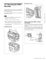
Chapter 2 Installation and Preparations 5 Rotate the accessory mount lever downward (pull it in the opposite direction of the lens when attaching to the top). FILTER ND 1 2 3 4 5 111CC///AL416EP64NANNDRDD CC A B C D E 534616233/20000N0000KKKKD 1 2 3 LOCK VF MENU/DISPLAY CANCEL/STATUS RUN 4 AUTO BBLAKL PAGE SET PRO LOCK OFF ON REMOTE To detach 1 Rotate the accessory clamp lever upward (toward the lens when attaching to the top) (1 in the figure below). 2 Release the lock by sliding the lock-release knob in the direction of the arrow (2 in the figure below) then pull up on the accessory mount lever (3 in the figure below) (pull it toward the lens when mounting on the top). Accessory clamp lever 6 While holding the lock-release knob in the direction of the arrow, fold the accessory mount lever into its home position. FILTER ND 1 2 3 4 5 C111C///LA416EP64NANNDRDD CC A B C D E 34615233/620000N0000KKKKD 1 2 3 LOCK VF MENU/DISPLAY CANCEL/STATUS MENETNEURSEL/ RUN 4 AUTO BBLAKL PAGE SET 1 2 PRO 3 LOCK OFF ON REMOTE FILTER ND 1 2 3 4 5 111CC///AL416EP64NANNDRDD CC A B C D E 534616233/20000N0000KKKKD 1 2 3 LOCK VF MENU/DISPLAY CANCEL/STATUS RUN 4 AUTO BBLAKL PAGE SET PRO 1 2 LOCK OFF ON REMOTE 7 Rotate the accessory clamp lever downward (toward the opposite direction of the lens when attaching to the top). Lock-release knob Accessory mount lever 3 While holding the safety release tab pressed inward, pull up on the interface box to disengage the connectors, then pull out the box horizontally. (When attaching to the top, hold the safety release tab pressed downward, slide the interface box toward the lens to disengage the connectors, then pull out the box vertically). Safety release tab FILTER ND 1 2 3 4 5 111CC///AL416EP64NANNDRDD CC A B C D E 534616233/20000N0000KKKKD 1 2 3 LOCK VF MENU/DISPLAY CANCEL/STATUS RUN 4 AUTO BBLAKL PAGE SET PRO LOCK OFF ON REMOTE LOLCOKCK FILTER ND 1 2 3 4 5 111CC///AL416EP64NANNDRDD CC A B C D E 34615233/620000N0000KKKKD 1 2 3 LOCK VF MENU/DISPLAY CANCEL/STATUS RUN 4 AUTO BBLAKL PAGE SET PRO 4 OFF ON 5 REMOTE 4 Return the accessory mount lever and accessory clamp lever to their home positions. 18 Mounting the Interface Box
-
 1
1 -
2
-
3
-
4
-
5
-
6
-
7
-
8
-
9
-
10
-
11
-
12
-
 13
13 -
 14
14 -
 15
15 -
 16
16 -
 17
17 -
 18
18 -
 19
19 -
 20
20 -
 21
21 -
 22
22 -
 23
23 -
24
-
25
-
26
-
27
-
28
-
29
-
30
-
31
-
32
-
33
-
34
-
35
-
36
-
37
-
38
-
39
-
40
-
41
-
42
-
43
-
44
-
45
-
46
-
47
-
48
-
49
-
50
-
51
-
52
-
53
-
54
-
55
-
56
-
57
-
58
-
59
-
60
-
61
-
62
-
63
-
64
-
65
-
66
-
67
-
68
-
69
-
70
-
71
-
72
-
73
-
74
-
75
-
76
-
77
-
78
-
79
-
80
-
81
-
82
-
83
-
84
-
85
-
86
-
87
-
88
-
89
-
90
-
91
-
92
-
93
-
94
-
95
-
96
-
97
-
98
-
99
-
100
-
101
-
102
 |
 |
