Sony F23 Product Manual (F23 Operation Manual 1st edition) - Page 17
Installation and Preparations, 2-1 Mounting the Interface Box, Mounting the, Interface Box
 |
View all Sony F23 manuals
Add to My Manuals
Save this manual to your list of manuals |
Page 17 highlights
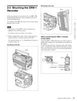
Chapter 2 Installation and Preparations LOLCOKCK Installation and Preparations 2 Chapter 2-1 Mounting the Interface Box 3 Release the lock by sliding the lock-release knob in the direction of the arrow (1 in the figure below) then pull up the accessory mount lever (pull it toward the lens when mounting on the top) (2 in the figure below). The supplied interface box can be attached to the top or rear of the camera head. Connection between the camera head and the interface box is achieved by mounting, eliminating additional cable connections. • The same attaching/detaching system is used both on the top and the rear. • The following instructions use the illustrations of attaching to the rear as examples. • Although the illustrations show the statuses where the L handle has been detached, the interface box can be mounted/unmounted with the L handle attached. To attach 1 Place the camera head on a stable, flat surface. 2 Rotate the accessory clamp lever upward (toward the lens when attaching to the top). Accessory clamp lever FILTER ND 1 2 3 4 5 C111C///LA416EP64NANNDRDD CC A B C D E 534616233/20000N0000KKKKD 1 2 3 LOCK VF MENU/DISPLAY CANCEL/STATUS RUN 4 AUTO BBLAKL PAGE SET PRO 1 2 OFF ON REMOTE Lock-release knob Accessory mount lever 4 Aligning the matching line on the interface box with that on the camera head, fit the interface box into the camera head then push down on the box (slide it in the opposite direction of the lens when attaching to the top) so that the connectors engage. FILTER ND 1 2 3 4 5 111CC///AL416EP64NANNDRDD CC A B C D E 534616233/20000N0000KKKKD 1 2 3 LOCK VF MENU/DISPLAY CANCEL/STATUS RUN 4 AUBTLOK BAL PAGE SET PRO OFF ON REMOTE FILTER ND 1 2 3 4 5 C111C///LA416EP64NANNDRDD CC A B C D E 534616233/20000N0000KKKKD 1 2 3 LOCK VF MENU/DISPLAY CANCEL/STATUS RUN 4 AUTO BBLAKL PAGE SET PRO OFF ON REMOTE Matching line on the camera head Matching line on the interface box 17 Mounting the Interface Box
-
 1
1 -
2
-
3
-
4
-
5
-
6
-
7
-
8
-
9
-
10
-
11
-
 12
12 -
 13
13 -
 14
14 -
 15
15 -
 16
16 -
 17
17 -
 18
18 -
 19
19 -
 20
20 -
 21
21 -
 22
22 -
23
-
24
-
25
-
26
-
27
-
28
-
29
-
30
-
31
-
32
-
33
-
34
-
35
-
36
-
37
-
38
-
39
-
40
-
41
-
42
-
43
-
44
-
45
-
46
-
47
-
48
-
49
-
50
-
51
-
52
-
53
-
54
-
55
-
56
-
57
-
58
-
59
-
60
-
61
-
62
-
63
-
64
-
65
-
66
-
67
-
68
-
69
-
70
-
71
-
72
-
73
-
74
-
75
-
76
-
77
-
78
-
79
-
80
-
81
-
82
-
83
-
84
-
85
-
86
-
87
-
88
-
89
-
90
-
91
-
92
-
93
-
94
-
95
-
96
-
97
-
98
-
99
-
100
-
101
-
102
 |
 |
